4
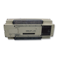
Indicators The following diagram shows the functions of the various indicators, taking
the C20P as an example.
8 9 10 11
0 1 2 3 4 5 6 7
OUTPUT 5 CH
POWER
INPUT 0 CH
OUTPUT: Shows whether the output is ON or OFF.
POWER: Stays lit while power is turned ON to the
I/O Unit.
INPUT: Shows whether the input ON or OFF.
0 1 2 3 4 5 6 7
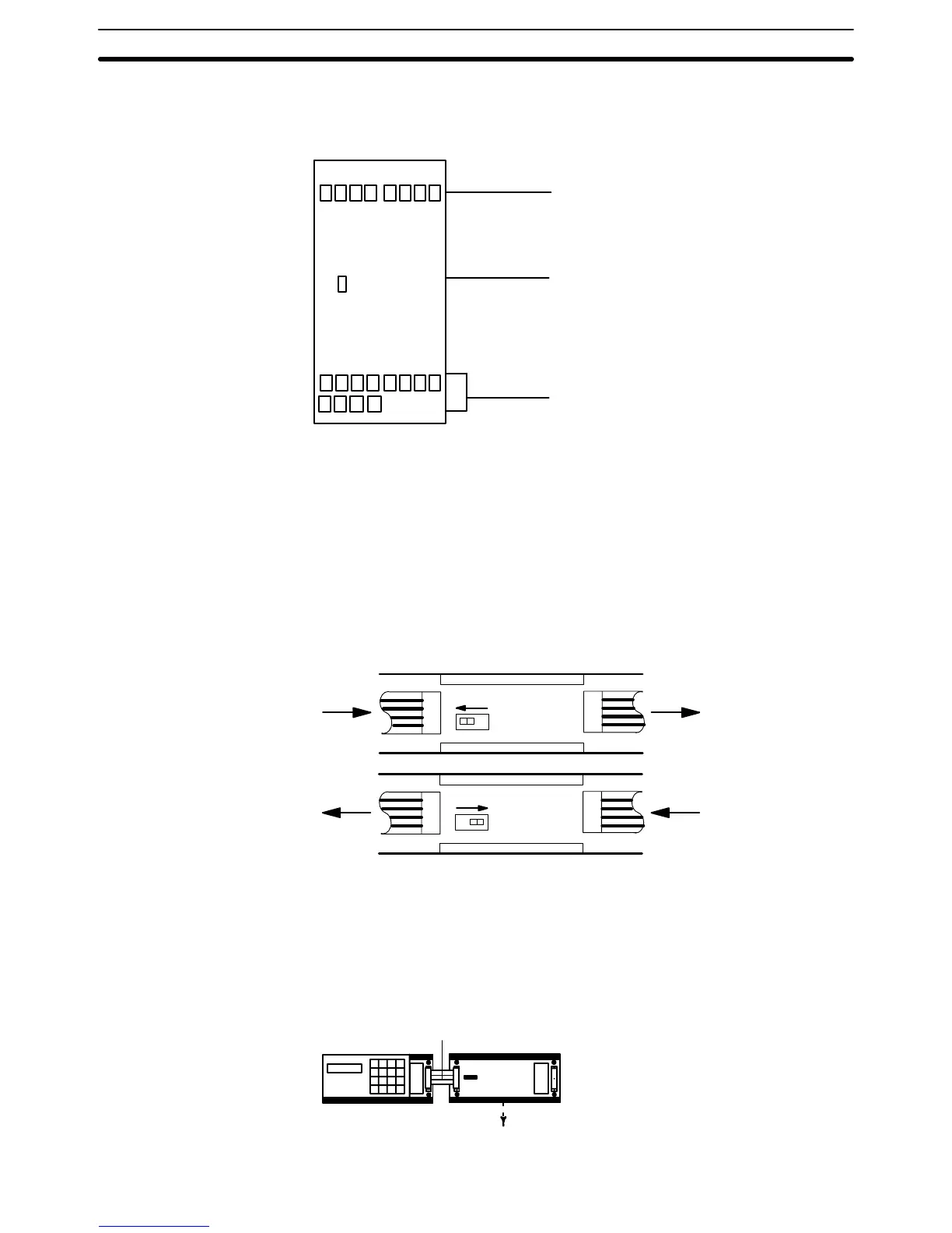
CPU Left/Right Selector The C20P, C28P, C40P, and C60P Expansion I/O Units all have CPU left/
right selector switches. The C16P and C4K do not. For those models which
have the switch, care must be taken to set it so that it corresponds with the
direction of the I/O Connecting Cable. If the switch is set in the wrong direc-
tion, the System will operate as if the I/O Unit were not there. Set the switch
so that the CPU connector side (Left or Right) is “in,” as shown in the follow-
ing diagram. Do not change the switch setting after power has been turned
ON, as this will cause the I/O bus to malfunction.
Lin Rout
To I/O
Link
Unit
From
CPU
LR
Rin Lout
To I/O
Link
Unit
From
CPU
LR
The following example diagrams show the proper switch settings for horizon-
tal and vertical mounting of Units.
Horizontal Mounting All Units can be positioned horizontally.
Set to Left in Right out
C20P-CN501
CPU
I/O Unit
Nomenclature Section 1-1
 Loading...