44
2-7 Special Wiring Precautions
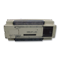
Emergency Stop Circuit An external relay circuit can be constructed to prevent a CPU breakdown or
malfunction from damaging the entire System. In the following diagram, SR
bit 1813 is always open when the CPU is operating. If the program is set up
as shown in the diagram, then output 0500 will be ON whenever the CPU is
in either RUN or MONITOR mode, and it will function as an output to monitor
whether the CPU is operating properly or not.
1813
0050
Example
Normally
open (NO)
RUN output
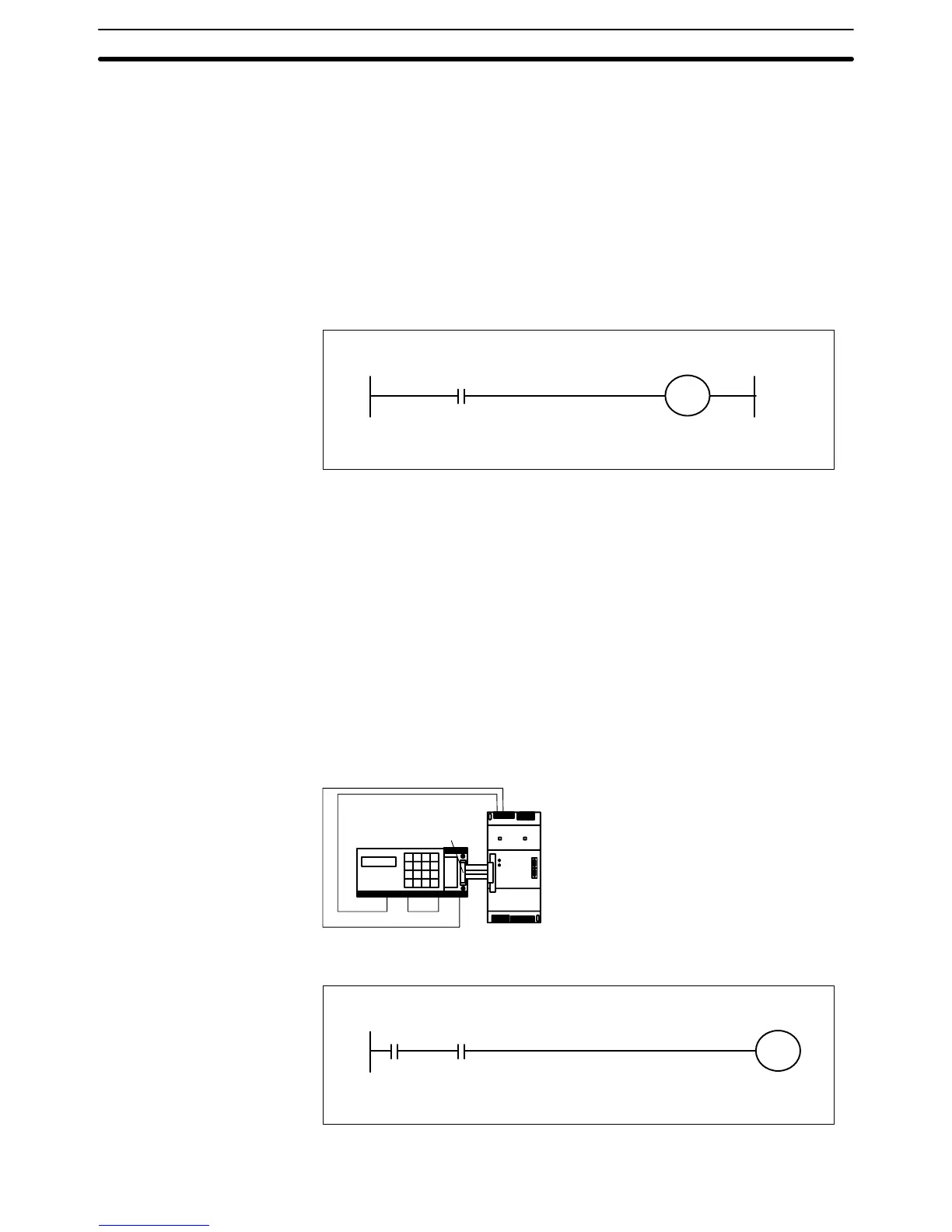
An I/O Link Unit’s RUN output terminal is wired to a CPU’s input terminal,
and can function as an output to monitor whether the entire PC System, in-
cluding the I/O Link Unit, is operating properly or not. In the diagram below,
the I/O Link Unit is connected to input terminal 0002. If the program is set up
as shown in the diagram, then output 0500 will be ON whenever the CPU is
in either RUN or MONITOR mode. The I/O Link Unit’s RUN output and the
CPU’s RUN or MONITOR output together comprise an AND in the external
relay circuit, and this can be used to construct an emergency stop circuit.
C20P
24 VDC
Output
0002
RUN output
I/O Link Unit
0002 1813
0050
Example
Normally
open (NO)
Emergency Stop Circuit
When an I/O Link Unit is
Used
Special Wiring Precautions Section 2-7
 Loading...