Medium & Heavy Payload Series-Hardware Installation Manual TM12/14 Series Hardware Version: 3.2 46
5. Electrical Interface
5.1 Overview
This chapter introduces all electrical interfaces of the robot arm and control box.
5.2 Electrical Warnings and Cautions
The application design and installation of the robot should comply with the following warnings.
DANGER:
1.
Ensure all pieces of the equipment are kept dry. If water enters the equipment, disconnect
the power and contact your supplier.
2. Only use the original cables included with the robot. If you need longer cables, contact
your supplier.
3. Ensure that the robot is properly grounded. If the grounding is not correct, it may cause a
WARNING:
The I/O cables used for the link between the control box and other pieces of equipment
should not be longer than 30 meters, unless testing shows that longer cables are feasible.
5.3 Control Box
WARNING:
Except for USB ports, other interfaces have to be installed while arm is powered off. Do not
install while arm is on to avoid abnormal shutdown.
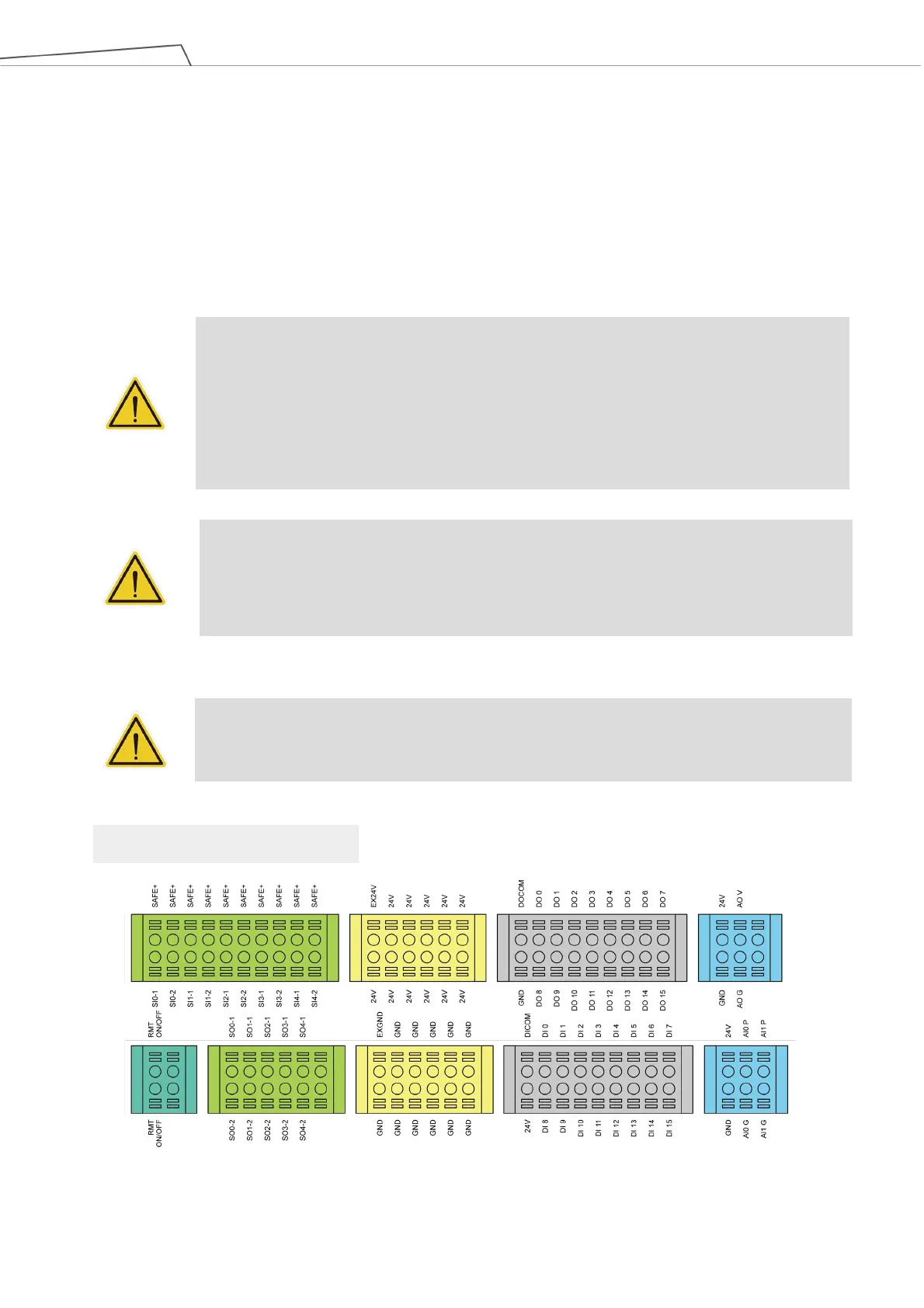
Figure 36: Control Box I/O Configuration (1/2)
Control Box I/O configuration
 Loading...