2
Frequency inverters
Type designation
200 V class
400 V class
Specifications
IP20 single-phase: CIMR-V7AZ B0P1 B0P2 B0P4 B0P7 B1P5 B2P2 B4P0
IP65 single-phase: CIMR-V7TZ --- --- B0P405 B0P705 B1P505 B2P205 ---
IP20 three-phase: CIMR-V7AZ 20P1 20P2 20P4 20P7 21P5 22P2 24P0
Maximum permissible motor output kW
1
1. Based on a standard 4-pole motor for maximum applicable motor output. Select the inverter model within the allowable motor rated current
0.12 0.25 0.55 1.1 1.5 2.2 4.0
Output
characteristics
Inverter capacity kVA
0.3 0.6 1.1 1.9 3.0 4.2 6.7
Rated output current A
0.8 1.6 3.0 5.0 8.0 11.0 17.5
Max. output voltage
Proportional to input voltage: 0..240 V
Max. output frequency
400 Hz
Power
supply
Rated input voltage
and frequency
Single-phase 200..240 V 50/60 Hz
3-phase 200..230 V 50/60 Hz
Allowable voltage
fluctuation
-15%..+10%
Allowable frequency
fluctuation
+5%
IP20 three-phase: CIMR-V7AZ
40P2 40P4 40P7 41P5 42P2 43P0 44P0 45P5 47P5
IP65 three-phase: CIMR-V7TZ
40P405 40P705 41P505 42P205 43P005 44P005
Maximum permissible motor output kW
1
1. Based on a standard 4-pole motor for maximum applicable motor output. Select the inverter model within the allowable motor rated current
0.37 0.55 1.1 1.5 2.2 3.0 4.0 5.5 7.5
Output
characteristics
Inverter capacity kVA
0.9 1.4 2.6 3.7 4.2 5.5 7.0 11.0 14.0
Rated output current A
1.2 1.8 3.4 4.8 5.5 7.2 9.2 14.8 18.0
Max. output voltage
Proportional to input voltage: 0..400 V
Max. output frequency
400 Hz
Power
supply
Rated input voltage
and frequency
3-phase 380..460 VAC, 50/60 Hz
Allowable voltage
fluctuation
-15%..+10%
Allowable frequency
fluctuation
+5%
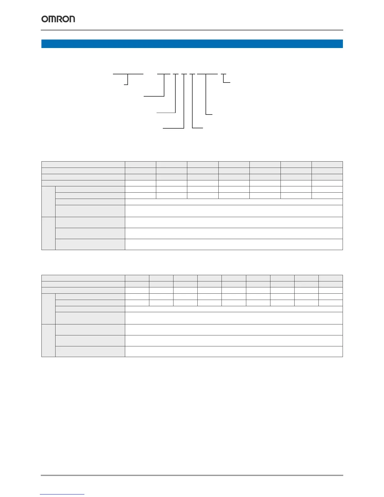
Voltage
B: Single-phase 200 VAC
2: Three-phase 200 VAC
4: Three-phase 400 VAC
Z: European standard specifications
Inverter
V7 series
A: With digital operator (with potentiometer)
T: V7 IP65 type with digital operator
( without potentiometer )
C I M R — V 7 A Z B 0 P 1 0
Max. applicable motor output
0P1: 0.1 kW
7P5: 7.5 kW
~
"P" indicates a decimal
point
[ ]
Protective enclosure:
0: IP20
1: NEMA1
05: IP65
Varispeed V7
3
Commom specifications
Model number
CIMR-V7AZ-@
CIMR-V7TZ-@
Specifications
Control functions
Control methods
Sine wave PWM (V/f control, sensorless vector control)
Output frequency range
0.1..400 Hz
Frequency tolerance
Digital set value: ±0.01% (-10..+50 ºC)
Analogue set value: ±0.5% (25 ±10 ºC)
Resolution of frequency set value
Digital set value: 0.01 Hz (<100 Hz), 0.1 Hz (>100 Hz)
Analogue set value: 1/1000 of maximum frequency
Resolution of output frequency
0.01 Hz
Overload capability
150%/60 s
Frequency set value
0..10 V (20 kΩ), 4..20 mA (250 Ω), 0..20 mA (250 Ω)
Pulse train input, frequency setting value (selectable)
Braking torque
(short term peak torque)
Up to 200 W 150% or more
550 W to 1.1 kW 100% or more
1.5 kW 50% or more
>1.5 kW 20% or more
Continuous braking torque approx. 20% without, 150% with external braking resistor
Functionality
Binary inputs
7 freely programmable inputs
Binary outputs
1 relay output, 2 freely programmable open collector outputs
Analogue output
1 programmable analogue output (0..10 V)/pulse output
Analogue inputs
2 analogue inputs, 0..10 V, 4..20 mA, 0..20 mA
Braking/acceleration times
0.01..6000 s
Display
Optionally frequency, current or set value
Error and status LED
Protection functions
Motor overload protection Electronic thermal overload relay
Instantaneous overcurrent Motor coasts to a stop at approx. 250% of inverter rated current
Overload Motor coasts to a stop after 1 minute at 150% of inverter rated output current
Overvoltage Motor coasts to a stop if DC bus voltage exceed 410 V (double for 400 V class)
Undervoltage
Stops when DC bus voltage is approx. 200 V or less (double for 400 V class)
(approx. 160 V or less for single-phase series)
Momentary power loss
Following items are selectable: not provided (stop if power loss is 15 ms or longer), continuous operation
if power loss is approx. 0.5 s or shorter, continuous operation
Cooling fin overheat Protected by electronic circuit
Stall prevention level Individual levels during accel/constant speed. Decel ON/OFF available. During decel enable/disable selectable.
Cooling fan fault Detected by electronic circuit (fan lock detection)
Ground fault Protected by electronic circuit (operation level is approx. 250% of rated output current)
Power charge indication
RUN lamp stays ON or digital operator LED stays ON until the DC bus voltage becomes 50 V or less.
(Charge LED is provided for 400 V)
Ambient conditions
Degree of protection
IP20, NEMA1, IP65
Cooling
Self cooling for 200 V 0.1..0.4 kW (3 or single phase) and for 400 V 0.2..0.75 kW
Cooling fan for 200 V 0.75 to 7.5 kW and for 400 V 1.5 to 7.5 kW
Ambient temperature
Open air mounting: -10 ºC..50 ºC
Wall mounting: -10 ºC..40 ºC
Ambient humidity
95% (without condensation)
Storage temperature
-20 ºC..+60 ºC (short-term temperature during transportation)
Installation
Indoor (no corrosive gas, dust, etc.)
Installation height
Max. 1000 m
Vibration
10 to 20 Hz, 9.8 m/s
2
max; 20 to 50 Hz, 2 m/s
2
max
 Loading...


