4
Frequency inverters
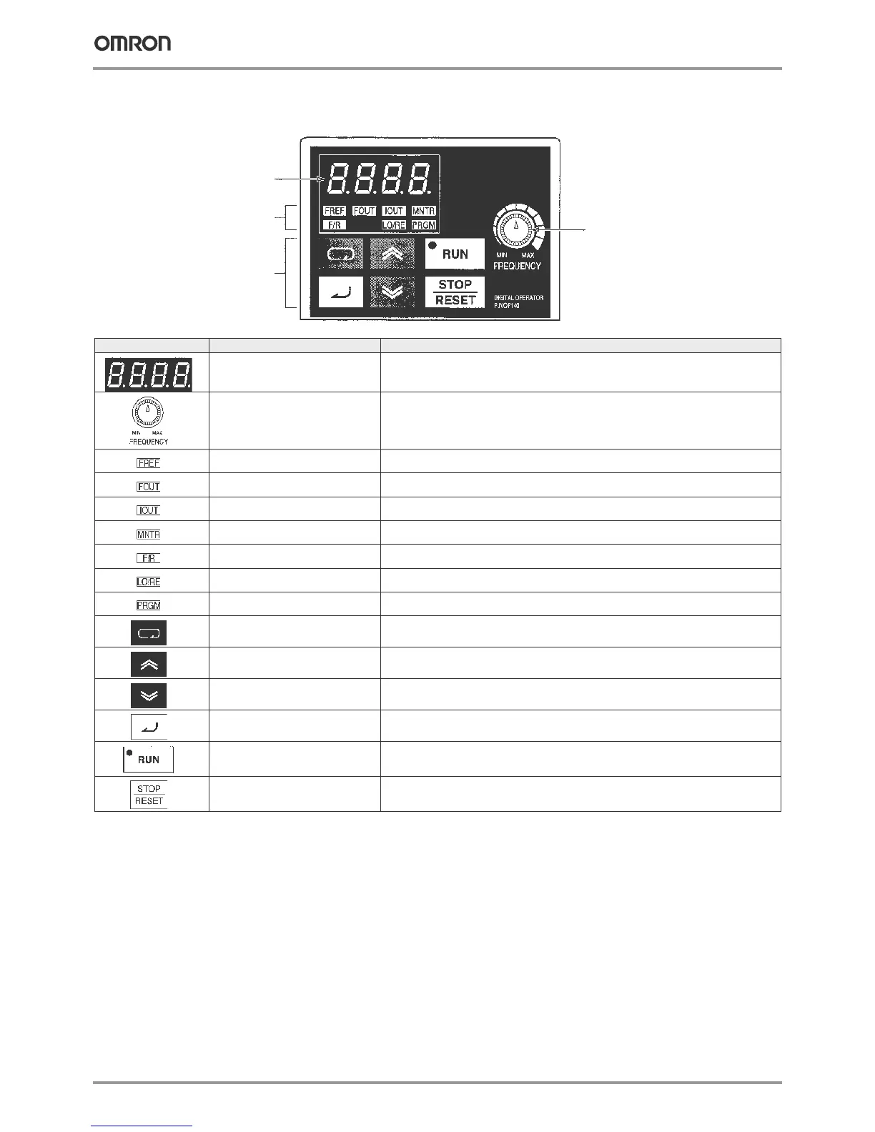
Digital operator
Indicators
(setting/monitor
item indicators)
Data display
FREQUENCY
adjuster
Operation keys
Appearance Name Function
Data display Displays relevant data items, such as frequency reference, output frequency,
and parameter set values.
Frequency adjuster Sets the frequency reference within a range between 0 Hz and the maximum frequency.
1
Frequency reference indicator The frequency reference can be monitored or set while this indicator is lit.
Output frequency indicator The output frequency of the inverter can be monitored while this indicator is lit.
Output current indicator The output current of the inverter can be monitored while this indicator is lit.
Multi-function monitor indicator The values set in U01 through U10 are monitored while this indicator is lit.
Forward/reverse selection indicator The direction of rotation can be selected while this indicator is lit when operating the inverter
with the RUN key.
Local/remote selection indicator The operation of the inverter through the digital operator or according to the set parameters is
selectable while this indicator is lit.
2
Parameter setting indicator The parameters in n001 through n179 can be set or monitored while this indicator is lit.
3
Mode key Switches the simplified-LED (setting and monitor) item indicators in sequence.
Parameter being set will be canceled if this key is pressed before entering the setting.
Increment key Increases multi-function monitor numbers, parameter numbers, and parameter set values.
Decrement key Decreases multi-function monitor numbers, parameter numbers, and parameter set values.
Enter key Enters multi-function monitor numbers, parameter numbers, and internal data values after they
are set or changed.
RUN key Starts the inverter running when the 3G3MV is in operation with the digital operator
STOP/RESET key Stops the inverter unless parameter n007 is set to disable the STOP key.
Used to reset the inverter when an error occurs.
4
1. V7 IP65 types have digital operator without frequency adjuster.
2. The status of the local/remote selection indicator can be only monitored while the inverter is in operation. Any RUN comand input is ignored while this
indicator is lit.
3. While inverter is in operation, the parameters can be only monitored and only some parameters can be changed. Any RUN command is ignored while the
parameter setting indicator is lit.
4. For safety reasons, the reset function cannot be used while an operation instruction (forward/reverse) is being input. Turn the operation instruction OFF
before using this function.
 Loading...


