UNDER-FLOOR
MOUNT
For an under-floor mount installation, the generator set
is mounted in a housing below the floor and outside the
coach of the recreational vehicle. This housing assem-
bly should be as supplied
or
approved by Onan, and
must be installed in accordance with safety approved
specifications. Review the following text for general
application information, and review the proper housing/
exhaust kit instructions for further specifics regarding
under-floor mount installations.
The vehicle construction must be able to support the
weight
of
the generator set (see General Specifications).
It is the vehicle manufacturer’s and the installer’s
responsibility to provide and assure
a
structurally sound
support frame, by using tubing, angle brackets, or with
steel reinforced plywood
or
other composition board.
Reinforcement of plywood
or
particle board can be with
3
inch
(76
mm)
or
larger washers
or
a full metal plate.
.-
General
Generator Set Location:
When choosing a location for
mounting the under-floor mount generator set, consider
the following not only for mounting, but for protection
of
the generator set as well.
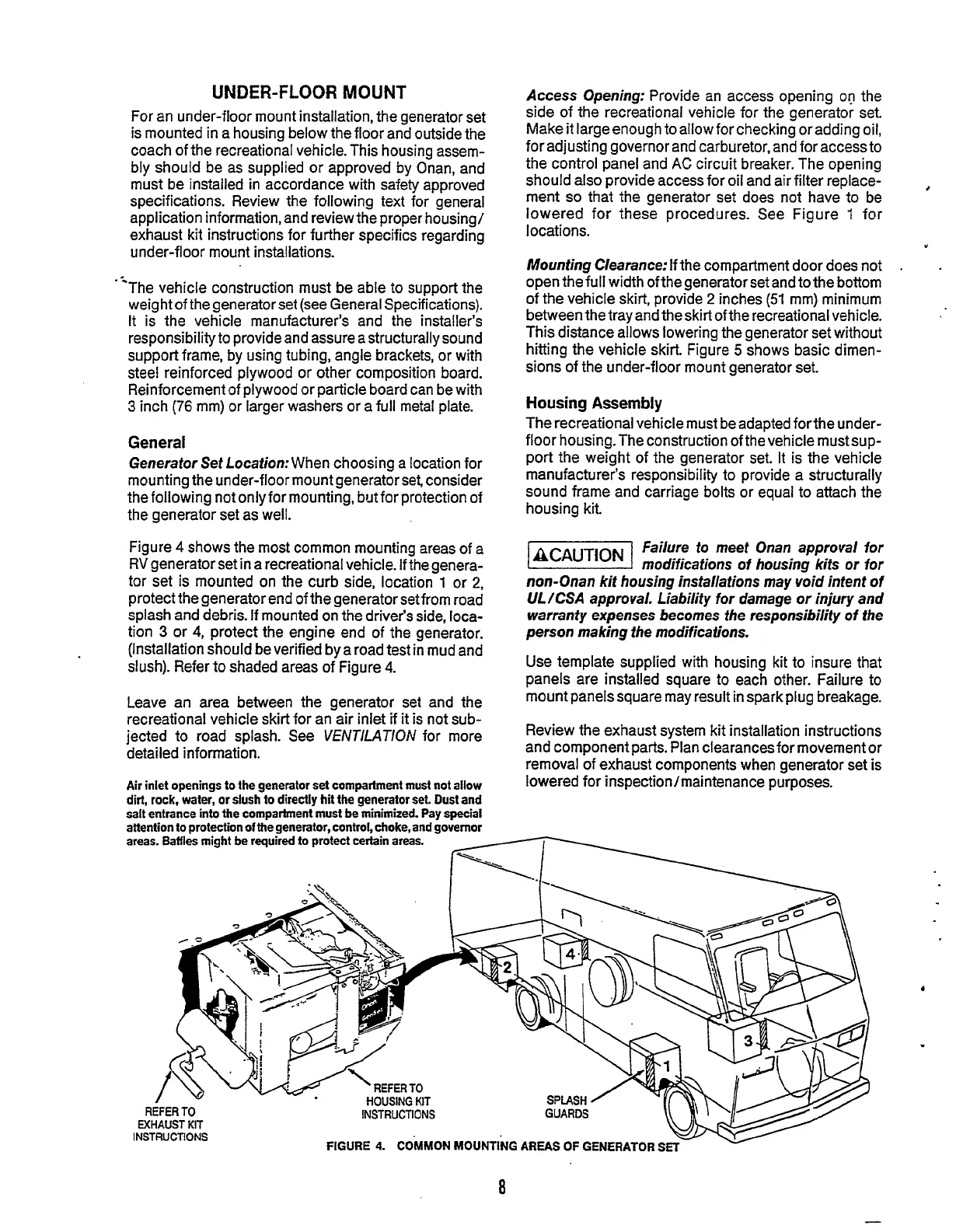
Figure
4
shows the most common mounting areas of a
RV
generator set in a recreational vehicle.
If
the genera-
tor set is mounted
on
the curb side, location
l
or
2,
protect the generator end of the generator set from road
splash and debris.
If
mounted on the driver’s side,
loca-
tion
3
or
4,
protect the engine end of the generator.
(Installation should be verified bya road test in mud and
slush). Refer to shaded areas of Figure
4.
Leave an area between the generator set and the
recreational vehicle skirt for an air inlet if
it
is not sub-
jected to road splash. See
V€NTlLATlON
for more
detailed information.
Air
inlet openings
to
the generator set compartment must not allow
dirt, rock, water, or slush to directly hit the generator
set.
Oust and
salt entrance into the compartment must
be
minimized. Pay special
attention to protection
of
the generator, control, choke, and governor
Access Opening:
Provide an access opening
og
the
side of the recreational vehicle for the generator set.
Make it largeenough to allow for checking
or
adding oil,
for adjusting governor and carburetor, and for access to
the control panel and
AC
circuit breaker. The opening
should also provide access for oil and air filter replace-
ment
so
that the generator set does not have to be
lowered for these procedures. See Figure
1
for
locations.
Mounting Clearance:
If the compartment door does not
.
open the full width of the generator set and to the bottom
of the vehicle skirt, provide
2
inches
(51
mm) minimum
between the tray and the skirt of the recreational vehicle.
This distance allows lowering the generator set without
hitting the vehicle skirt. Figure
5
shows basic dimen-
sions
of
the under-floor mount generator set.
8
Y
Housing Assembly
The recreational vehicle must be adapted forthe under-
floor housing. The construction of the vehicle must sup-
port the weight of the generator set. It is the vehicle
manufacturer‘s responsibility to provide a structurally
sound frame and carriage bolts
or
equal to attach the
housing kit.
failure to meet Onan approval for
modifications
of
housing kits or for
non-Onan kit housing installations may void intent
of
ULKSA
approval. Liability for damage or injury and
warranty expenses
becomes
the responsibility of
the
person making the modifications.
Use template supplied with housing kit to insure that
panels are installed square to each other. Failure to
mount panels square may result in spark plug breakage.
Review the exhaust system kit installation instructions
and component parts. Plan clearancesfor movement or
removal of exhaust components when generator set is
lowered for inspection/maintenance purposes.
areas.
Baffi&
might be required
to
protect certain areas.
~
REFER
TO
INSTRUCTIONS
EXHAUST
KIT
INSTRUCTIONS
FIGURE
4.
COMMON
MOUNTING
AREAS
OF
GENERATOR
s
Redistribution or publication of this document,
by any means, is strictly prohibited.
 Loading...
