Ventilation
and
Acoustics
VENTILATION
The most important factors
of
ventilation for an
RV
air-
cooled generator set are sufficient incoming air (for
combustion and cooling) and adequate exhausting of
heated air.
All
Onan generator sets for recreational veh-
icles
use Vacu-Flo@ cooling.
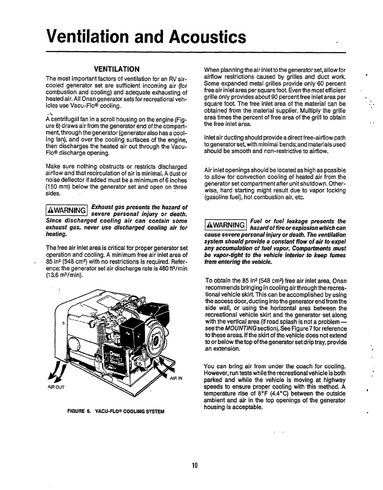
Acentrifugal fan in a scroll housing on the engine (Fig-
ure
6)
draws air from the generator end of the compart-
ment, through the generator (generator also has a cool-
ing fan), and over the cooling surfaces of the engine,
then discharges the heated air out through the Vacu-
Floe
discharge opening.
Make sure nothing obstructs or restricts discharged
airflow and that recirculation
of
air is minimal.
A
dust or
noise deflector
if
added must be a minimum of
6
inches
(150
mm) below the generator set and open on three
sides.
Exhaust gas presenfs the hazard
of
(BWARNINGI
severe personal injury
or
death.
Since discharged cooling air can contain some
exhaust gas, never use discharged cooling air for
heating.
The free air inlet area is critical
for
proper generator set
operation and cooling.
A
minimum free air inlet area of
85
in2
(548
cm2) with no restrictions is required. Refer-
ence: the generator set air discharge rate is
480
ft3/min
(1
3.6
m3/min).
-
FIGURE
6.
VACU-FLO@
COOLING
SYSTEM
When planning the air inletto thegenerator set,allowfor
airflow restrictions caused by grilles and duct work.
Some expanded metal grilles provide only
60
percent
free air inlet area per square foot. Even the most efficient
grille only provides about
90
percent free inlet area per
square foot The free inlet area of the material can be
obtained from the material supplier. Multiply the grille
area times the percent
of
free area
of
the grill to obtain
the free inlet area.
Inlet air ducting should provide a direct free-airflow path
to generator set, with minimal bends; and materials used
should be smooth and non-restrictive to airflow.
Air inlet openingsshould be located as high as possible
to allow for convection cooling of heated air from the
generator set compartment after unit shutdown. Other-
wise, hard starting might result due to vapor locking
(gasoline fuel), hot combustion air, etc.
Fuel or fuel leakage presents the
IBWAR”G1
hazardof fire
or
explosion which can
cause severe personal injury or death. The ventilation
system should provide a constant flow of air
to
expel
any accumulation of fuel vapor. Compartments must
be
vapor-tight to the vehicle interior
to
keep fumes
from entering the vehicle.
To
obtain the
85
in2
(548
cm2) free air inlet area, Onan
recommends bringing in cooling airthtough the recrea-
tional vehicle skirt. This can be accomplished by using
the access door, ducting intothe generator end from the
side wall, or using the horizontal area between the
recreational vehicle skirt and the generator set along
with the vertical area (if road splash
is
not a problem
-
see the MOUNTINGsection).See Figure 7for reference
to these areas. If the skirt of the vehicle does not extend
to or below the
top
of the generator set drip tray, provide
an extension.
You
can bring air from under the coach for cooling.
However, run tests while the recreational vehicle
is
both
parked and while the vehicle is moving at highway
speeds to ensure proper cooling with this method.
A
temperature rise of
8°F
(4.4OC)
between the outside
ambient and
air
in
the top openings of the generator
housing
is
acceptable.
I
..
..
,
b
..
10
Redistribution or publication of this document,
by any means, is strictly prohibited.