3. Location and Mounting
3-1
GENERAL
Read the entire manual and housing/exhaust kit in-
structions before installing the genset. The genset
is designed for two very different types of installa-
tion: conventional compartment mount installation
and under-floor mount installation. Choose the ap-
propriate section and carefully follow the instruc-
tions given.
COMPARTMENT MOUNT
In a conventional installation, the genset is installed
on a framework that is part of the vehicle. This
framework must be constructed in accordance with
the safety-approved specifications contained in the
Compartment Construction
section following.
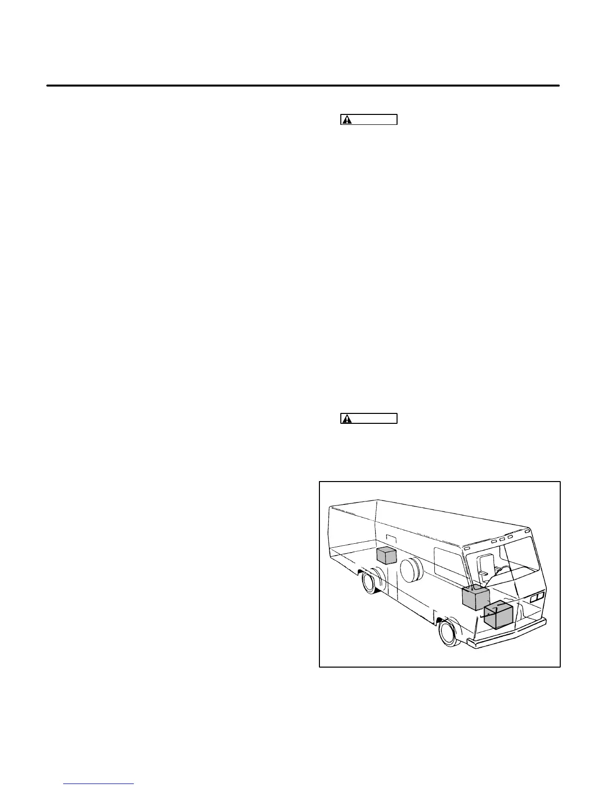
Unless the genset is to be removed from under-
neath the vehicle, plan the location for an access
opening to be large enough to permit genset remov-
al. Typical locations are illustrated in Figure 3-1. Al-
low additional clearance for easy access to the oil
fill, drain, filter, and oil dipstick, as well as the air
cleaner element, circuit breaker, governor adjust-
ments, carburetor adjustments, spark plugs, Start/
Stop switch, and DC fuse. The locations of each are
shown in Figure 1-1 on Page 1-2.
Design the compartment large enough for the gen-
set to have a minimum clearance of 0.6 inch (15
mm) between the genset and compartment walls
and ceiling (and acoustical material, if used). See
Figures 9-4, 9-5, 9-7, and 9-9 on Pages 9-4, 9-5,
9-7, and 9-9 in Section
9. Outline Drawings
for gen-
eral information when reviewing the following and
refer to the specific Outline Drawing when perform-
ing installation.
Compartment Construction
1. It is imperative that the genset compartment be
separated from the living quarters and any fuel
(gasoline or propane) supply with a vapor-tight,
fire-resistant barrier. See the appropriate fig-
ures in Section
9. Outline Drawings
(and spe-
cific Outline Drawing) for minimum clearances
and compartment size.
WARNING
EXHAUST GAS IS DEADLY.
Construct a suitable vapor barrier of ap-
proved materials between the genset and
vehicle interior to keep out exhaust gas.
2. Line the compartment with 26-gauge galva-
nized steel or a material of comparable
strength, durability, and fire resistance (see
NFPA 70, NEC and California Title 25 for com-
plete details).
3. Construct the compartment floor in a manner
so as to prevent oil, fuel, or water accumula-
tion. Compartment drainage to the outside of
the vehicle can be accomplished by 1/2-inch
(13 mm) diameter holes as shown on the
compartment floor drawings in Section
9. Out-
line Drawings
.
NOTE: Do
not
use absorbent sound proofing
material on compartment floor. The floor should
have minimal openings to reduce sound level.
4. Equip the base with an oil drain hole to the out-
side on the compartment. Do not mount the
muffler below the oil drain hole.
WARNING
Fire presents the hazard of se-
vere personal injury or death. To prevent a
fire hazard, do not position the muffler di-
rectly below the drain hole.
FIGURE 3-1. TYPICAL GENSET LOCATIONS
5. Secure the genset mounting plate to the sup-
port frame using 3/8-16 UNC, grade 5 screws.
The back two mounting holes are supplied with
 Loading...