4. Ventilation and Acoustics
4-1
WARNING
EXHAUST GASES ARE DEADLY!
Never sleep in the vehicle with the genset run-
ning unless the vehicle is equipped with an op-
erating carbon monoxide detector with an audi-
ble alarm.
WARNING
Provide an adequate exhaust sys-
tem to properly expel discharged gases. In-
spect exhaust system daily for leaks per the
maintenance schedule. Check that exhaust
manifolds are secure and not warped. Do not
use exhaust gases to heat a compartment.
WARNING
Be sure the unit is well ventilated.
VENTILATION
The most important factors of ventilation for an RV
air-cooled genset are sufficient incoming air (for
combustion and cooling) and adequate exhausting
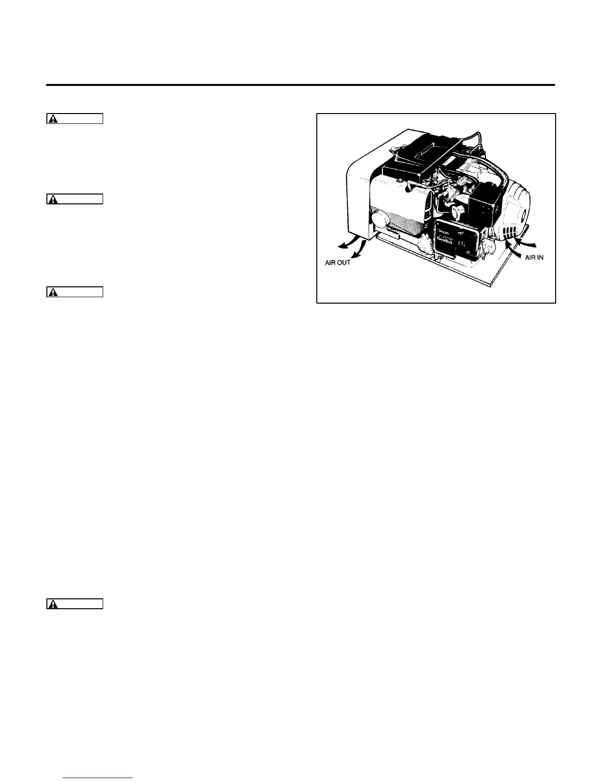
of heated air. The BGE/NHE genset uses Vacu-
Flo cooling.
A centrifugal fan in a scroll housing on the engine
(Figure 4-1) draws air from the generator end of the
compartment, through the generator (the generator
also has a cooling fan), and over the cooling sur-
faces of the engine. Then, it discharges the heated
air out through the Vacu-Flo discharge opening.
Make sure nothing obstructs or restricts discharged
airflow and that recirculation of air is minimal. A dust
or noise deflector, if added, must be a minimum of 3
inches (76 mm) below the genset and open on three
sides.
WARNING
Exhaust gas presents the hazard of
severe personal injury or death. Because dis-
charged cool air can contain some exhaust gas,
never use discharged cooling air for heating.
FIGURE 4-1. VACU-FLO
COOLING SYSTEM
The air inlet area is critical for proper genset opera-
tion and cooling. A minimum air inlet area of 85 in
2
(548 cm
2
) with no restrictions is required. Refer-
ence: the genset air discharge rate is 480 ft
3
/min
(13.6 m
3
/min).
When planning the air inlet to the genset, allow for
airflow restrictions caused by grilles and duct work.
Some expanded metal grilles provide only 60 per-
cent free air inlet area per square foot. Even the
most efficient grille only provides about 90 percent
free inlet area per square foot. The free air inlet area
of the material can be obtained from the material
supplier. Multiply the grille area times the percent of
free area of the grill to obtain the free inlet area.
Inlet air ducting should provide a direct, free, air-
flow path to the genset, with minimal bends. Materi-
als used should be smooth and non-restrictive to
airflow.
Air inlet openings should be located as high as pos-
sible to allow for convection cooling of heated air
from the genset compartment after unit shutdown.
Otherwise, hard starting might result due to vapor
locking (gasoline fuel), hot combustion air,
etc.
 Loading...