3-2
weld nuts to facilitate installing screws. The
front two holes can be secured with 3/8-16
screws, lock-washers, and nuts. The front
holes are square to allow the use of 3/8-16
cage nuts, if desired. See the appropriate fig-
ure in Section
9. Outline Drawings.
CAUTION
Road vibrations can cause
component damage to the genset if the unit
mounting plate is not fastened securely to
the vehicle compartment. Use screws of
sufficient length to allow a minimum of 1
1
/
2
threads to extend through the nut for maxi-
mum holding power.
UNDER-FLOOR MOUNT
In an under-floor mount installation, the genset is
mounted in a housing below the floor and outside
the vehicle coach. This housing assembly should
be as supplied or reviewed by Onan, and must be
installed in accordance with the Installation Codes
and Safety Recommendations list in the
Introduc-
tion.
Review the following text for general applica-
tion information, and review the proper housing/ex-
haust kit instructions for further specifics regarding
under-floor mount instructions.
The vehicle construction must be able to support
the weight of the genset (see
General Specifica-
tions).
It is the vehicle manufacturer’s and the in-
staller’s responsibility to provide a structurally
sound support frame, by using tubing, angle brack-
ets, or steel reinforced plywood or other composi-
tion board. Reinforcement of plywood or other com-
position board can be accomplished with 3-inch (76
mm) or larger washers or a full metal plate.
WARNING
Design the genset support struc-
ture carefully to prevent the genset from falling
from the vehicle and possibly causing a serious
road accident.
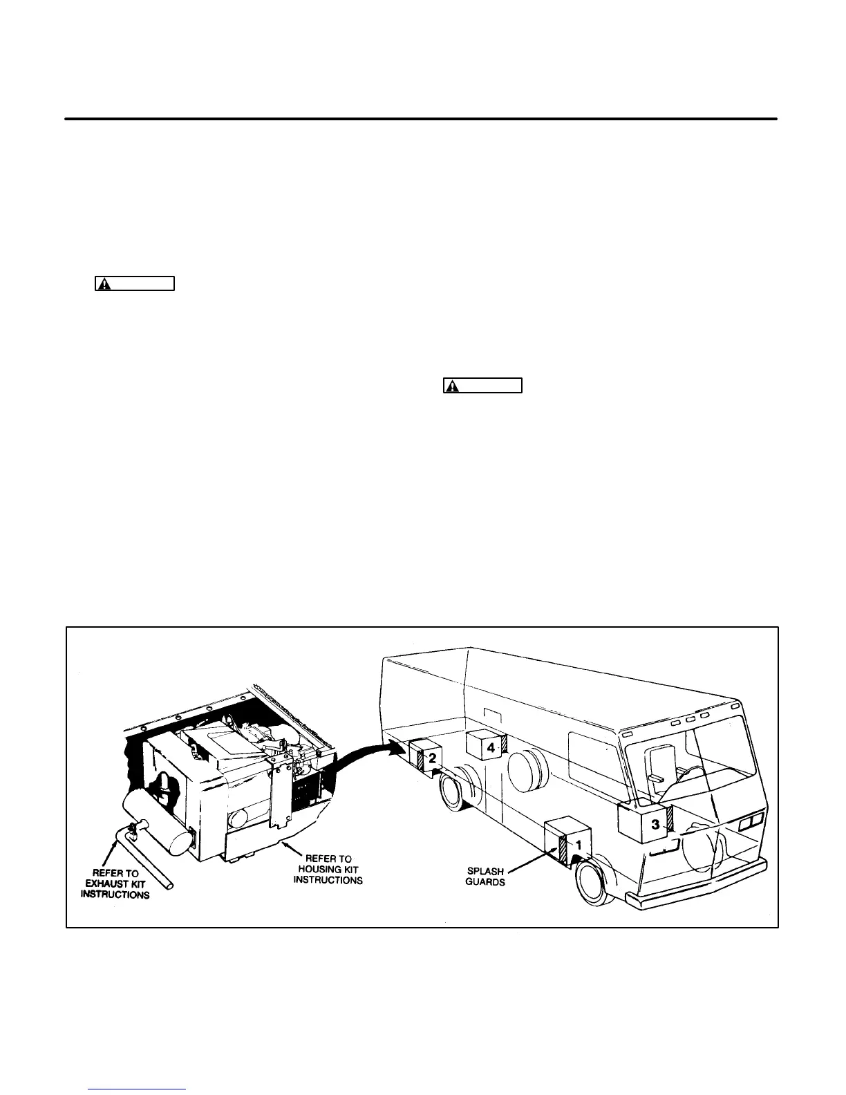
General
Genset Location.
When choosing a location for
mounting the under-floor mount genset, consider
the following not only for mounting, but for protec-
tion of the genset, as well. Figure 3-2 shows the
most common mounting areas of an RV genset in a
recreational vehicle.
FIGURE 3-2. COMMON UNDER-FLOOR MOUNTING AREAS OF GENSET
 Loading...