inward). Drive the new seal flush with the-rearsurface
of the bearing plate. Leave the seal installeron during
bearing plate installation to protect the oil seal.
Lubricate lips with heavy (high temperature) grease.
Install the crankshaft as follows. After each step, turn
the crankshaft to be sure
it
has not seized.
1.
Press front and rear main bearings into place;
align bearing and bearing housing oil holes.
Do
not attempt to drive a bearing into a cold block or
rear bearing plate. Install thrust washers and
locking pins.
2.
Oil bearing surfaces and install crankshaft from
rear
of
crankcase, through
rear bearing plate
hole.
3. Mount and secure rear bearing plate with same
thickness of new gaskets as removed.
4. Heat crank gear to about 350°F. Install key on
crankshaft, then drive gear into place. Install
retaining washer and lock ring.
5.
FOUR
CYLINDER
ONLY.
Set upper half
of
center
main housing
on
crankshaft and rotate it into
place. Be sure side marked FRONT is toward
crankshaft gear. Set two positioning dowels on
upper bearing mount. Install center main bearing
cap and torque bolts to
97-102
Ib. ft. (Figure
86).
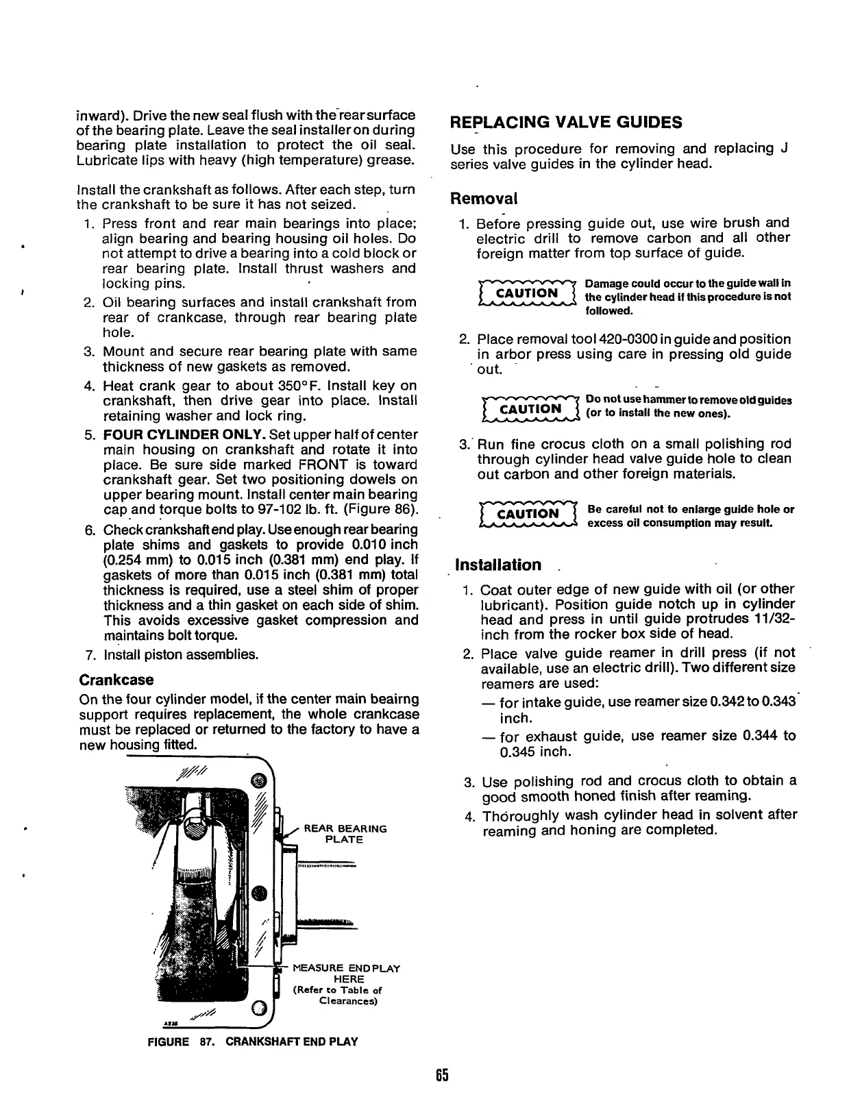
6.
Check crankshaft end play. Useenough rear bearing
plate shims and gaskets to provide
0.010
inch
(0.254 mm) to
0.015
inch
(0.381
mm) end play.
If
gaskets of more than
0.015
inch
(0.381
mm) total
thickness is required, use a steel shim of proper
thickness and a thin gasket on each side of shim.
This avoids excessive gasket compression and
maintains bolt torque.
7.
Install piston assemblies.
.
4
Crankcase
On the four cylinder model,
if
the center main beairng
support requires replacement, the whole crankcase
must be replaced or returned to the factory to have a
new housing fitted.
P
(Refer
eo
Table
of
Clearances)
REPLACING
VALVE
GUIDES
Use this procedure for removing and replacing
J
series valve guides
in
the cylinder head.
Removal
1.
Before pressing guide out, use wire brush and
electric drill to remove carbon and all other
foreign matter from top surface of guide.
Damage could occur to the guide wall in
the cylinder head
if
this procedure
is
not
followed.
2.
Place removal tool 420-0300 in guide and position
in arbor press using care in pressing old guide
.
out.
.-
Do
not
use
hammer to remove old guides
(or to install the new ones).
3.' Run fine crocus cloth on a small polishing rod
through cylinder head valve guide hole to clean
out carbon and other foreign materials.
Be careful not to enlarge guide hole or
excess oil consumption
may
result.
Installation
.
1.
Coat outer edge of new guide with oil (or other
lubricant). Position guide notch up
in
cylinder
head and press in until guide protrudes
11/32-
inch from the rocker box side of head.
2.
Place valve guide reamer in drill press (if not
available, use an electric drill). Two different size
reamers are used:
-
for intake guide, use reamer size
0.342
to
0.343-
-
for exhaust guide, use reamer size 0.344 to
inch.
0.345 inch.
3. Use polishing rod and crocus cloth to obtain a
4. Thoroughly wash cylinder head
in
solvent after
good
smooth honed finish after reaming.
reaming and honing are completed.
I,y
,/
WJ
FIGURE
87.
CRANKSHAFT END
PLAY
65
Redistribution or publication of this document,
by any means, is strictly prohibited.
 Loading...


