Three different types of ignition systems cover the
manual- and electric-starting models on two- and
four-cylinder engines. The manual-starting two-
cylinder model
(JB-M)
uses a magneto system. The
two -cy
I
i
n
d e r rem
o
te and e
I
ec t r
i
c
-s
ta rt
i
n g en g
in
es
(JB-R, JB-E) use a battery ignition system. The four-
cylinder model (JC) uses a battery ignition system
with an automotive distributor. For details of specially
suppressed systems (not covered here), request
su p p ression draw
i
n g
.
TESTING
Remove each plug, install the ignition wire to each
plug and hold the plug base against bare engine
metal. Crank the engine and watch the spark. A good
blue spark indicates a healthy ignition system, a weak
or yellow spark or no spark indicates a poor ignition
system. Defective ignition can be caused by defective
breaker points, coil condenser, or wiring. A good
spark on all but one cylinder indicates a defective
spark plug or a defective high tension wire.
BATTERY IGNITION
(JB
Electric and
Remote Starting Engines)
This model (Figure 35) uses a single coil 'battery
ignition to fire both spark plugs simultaneously. One
spark plug fires on the exhaust stroke while the other
is firing at the end of the compression stroke.
A
spark
advance on the breaker point mechanism advanc.es
the spark from SOATC (after top center) at cranking
speed, to
25"
BTC (before top center) when running
at rated speed; Figure 36.
Advance
10
degrees more for gas fuel.
CONTROL
BOX
Maintenance
Periodic maintenance should include:
1.
Checking ignition breaker point gap.
2.
Checking and cleaning spark plugs.
3.
Inspecting both low and hi-tension wiring.
4.
Checking ignition timing.
The JB engine with a flywheel magneto must always fire at
25"BTC, regardless
of
type
of
fuel. The JB engines have an
automatic advance
of
30";
the JC engines 26'.
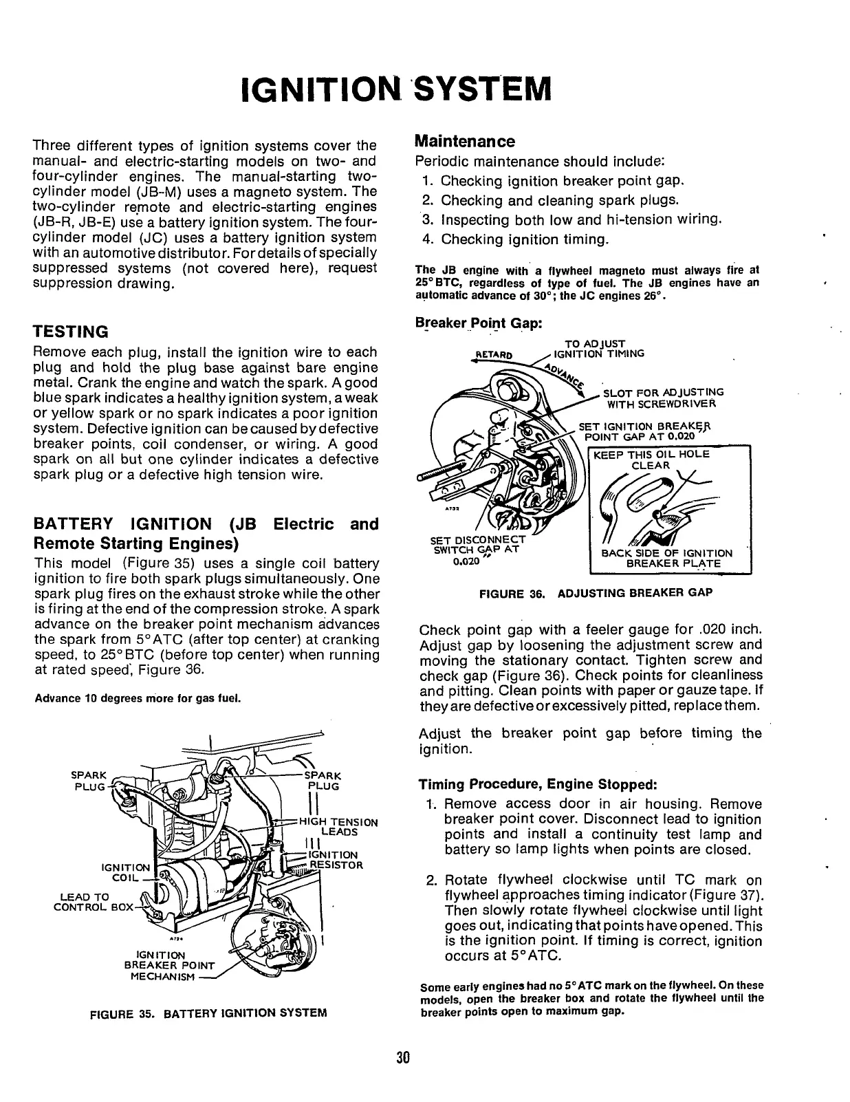
B!eaker_Point Gap:
TO ADJUST
IGNITION TIMING
SLOT
FOR
ADJUSTING
/
WITH
SCREWDRIVER
~
ET
IGNITION BREAKYP
POINT GAP AT
0.020
BACK SIDE
OF
IGNITION
BREAKER PLATE
SET DISCONNECT
SWITCH
qp
AT
0.020
I
..
I
FIGURE
36.
ADJUSTING BREAKER GAP
Check point gap with a feeler gauge for
.020
inch.
Adjust gap by loosening the adjustment screw and
moving the stationary contact. Tighten screw and
check gap (Figure 36). Check points for cleanliness
and pitting. Clean points with paper or gauze tape. If
they are defective or excessively pitted, replace them.
Adjust the
breaker point gap before timing the
ignition.
Timing Procedure, Engine Stopped:
1.
Remove access door in air housing. Remove
breaker point cover. Disconnect lead to ignition
points and install a continuity test lamp and
battery
so
lamp lights when points are closed.
2.
Rotate flywheel clockwise until TC mark on
flywheel approaches timing indicator (Figure
37).
Then slowly rotate flywheel clockwise until light
goes out, indicating that points haveopened. This
is the ignition point. If timing is correct, ignition
occurs at 5"ATC.
FIGURE
35.
BATTERY IGNlTlON SYSTEM
Some early engines had no VATC mark on the flywheel. On these
models, open the breaker box and rotate the flywheel until the
breaker points open to maximum gap.
Redistribution or publication of this document,
by any means, is strictly prohibited.
 Loading...


