ENGINE
DISASSEMBLY
AND
REPAIR
Intake
Exhaust
This section covers the various assemblies and parts
Of the engine. All repairs should be done by a
competent mechanic.
Maintain factory limits and
clearances (see
Dimensions and Clearances
section).
PRIOR
SPEC
D
BEGIN SPEC
D
.
GASOLINE
.010
.012
.013
.015
GAS, GAS-GASOLINE
CYLlNDER HEADS AND VALVES
Each cylinder head assembly contains valves, valve
seat inserts and guides, rocker arms and spark plugs.
The valve assemblies are operated by pushrods
running through the cylinder head and push rod
shields to the camshaft. Exhaust valves are hardened
chrome alloy-faced, and ride on hardened chrome-.
alloy seat inserts. AI1 valves have release-type
rotators.
Check the valve clearances at regular intervals.
In
addition, scrape the combustion chambers clean and
inspect the valves and valve seats regularly. If the
combustion chambers show excessive carbon
buildup, reduce the interval between cleaning.
Adjustment
After the engine has reached a stable temperature
condition, the valve clearances may be adjusted.
It
is
recommended that the valve clearance be set with
engine at room temperature (approximately
75O
F).
Allow at least two hours cooling time after engine
operation.
JB
Series
Adjust valve clearance on the
JB
engines as follows,
obtaining valve clearances from Table 4.
1.
Turn the flywheel
so
the piston of the valve to be
checked is between 10 degrees and 45 degrees
after TDC (about 2 inches after TDC) of the
co m p ression stroke.
2. Turn the flywheel until the TC (top center) mark
on the flywheel lines up with thetiming pointeron
the gear cover. Then turn the flywheel
in
a
clockwise direction for an additional 10 to
45
degrees. There is no timing mark for this position
so
it must be estimated. With the piston located in
this position the cylinder will be in its power
stroke with both valves completely closed.
3. Check the cylinder head-bolt torque.
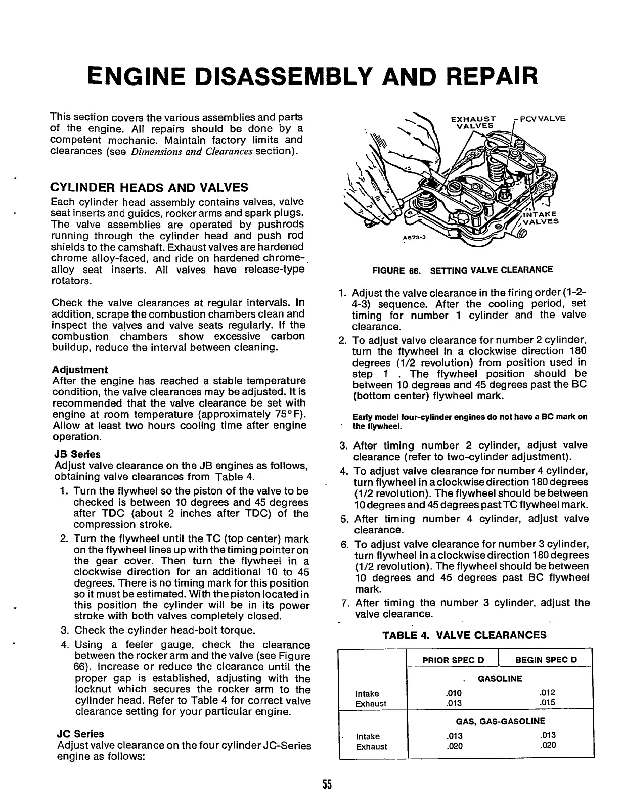
4. Using a feeler gauge, check the clearance
between the rocker arm and the valve (see Figure
66).
Increase or reduce the clearance until the
proper gap is established, adjusting with the
locknut which secures the rocker arm to the
cylinder head. Refer to Table 4 for correct valve
clearance setting for your particular engine.
JC Series
Adjust valve clearance on the four cylinder JC-Series
engine as follows:
W
FIGURE
66.
SETTING VALVE CLEARANCE
.
Intake
I
Exhaust
I
.013
.020
I
I
I
55
Redistribution or publication of this document,
by any means, is strictly prohibited.
 Loading...


