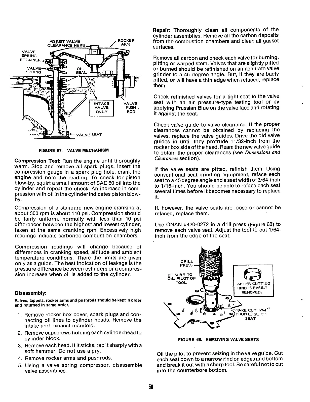
VALVE SEAT
FIGURE
67.
VALVE MECHANISM
Compression Test:
Run the engine until thoroughly
warm. Stop and remove all spark plugs. Insert the
compression gauge in a spark plug hole, crank the
engine and note the reading.
To
check for piston
blow-by, squirt a small amount of SAE
50
oil into the
cylinder and repeat the check. An increase in com-
pression with oil in thecylinder indicates piston blow-
Compression of a standard new engine cranking at
about
300
rpm is about 110 psi. Compression should
be fairly uniform,
normally with less than
10
psi
differences between the highest and lowest cylinder,
taken at the same cranking rpm. Excessively high
readings indicate carboned combustion chambers.
by.
Compression readings will change because
of
differences in cranking speed, altitude and ambient
temperature conditions. There the limits are given
only as a guide. The best indication of leakage is the
pressure difference between cylinders or a compres-
sion increase when oil is added to the cylinder.
Disassembly:
Valves, tappets, rocker arms and pushrods should be kept in order
and returned In same order.
1.
2.
3.
4.
5.
Remove rocker box cover, spark plugs and con-
necting oil lines to cylinder heads. Remove the
intake and exhaust manifold.
Remove capscrews holding each cylinder,head to
cylinder block.
Remove each head.
If
it sticks, rap it sharply with a
soft hammer.
Do
not use a pry.
Remove rocker arms and pushrods.
Using a valve spring compressor, disassemble
valve assemblies.
Repair:
Thoroughly clean all components
of
the
cylinder assemblies. Remove all the carbon deposits
from the combustion chambers and clean all gasket
surfaces.
Remove all carbon and check each valve for burning,
pitting or warped stem. Valves that are slightly pitted
or burned should be refinished on an accurate Valve
grinder to a 45 degree angle. But, if they are badly
pitted, or will have a thin edge when refaced, replace
them.
Check refinished valves for a tight seat to the valve
seat with an air pressure-type testing tool or by
applying Prussian Blue on the valve face and rotating
it
against the seat.
Check valve guide-to-valve clearance. If the proper
clearances cannot be obtained by replacing the
valves, replace the valve guides. Drive the old valve
guides in until they protrude 11/32-inch from the
rocker box side
of
the head. Ream the new valve guide
to obtain the proper clearances (see
Dimensions and
Clearances
section).
If
the valve seats are pitted, refinish them. Using
conventional seat-g rind
i
ng equipment, reface each
seat to a45degreeangleand aseatwidthof3/64-inch
to 1/16-inch. You should be able
to
reface each seat
several times before
it
becomes necessary to replace
it.
If, however, the valve seats are loose or cannot be
refaced, replace them.
Use ONAN #420-0272 in a drill press (Figure 68) to
remove each valve seat. Adjust the tool to cut 1/64-
inch from the edge
of
the seat.
OIL PILOT
OF
FIGURE
68.
REMOVING VALVE SEATS
Oil the pilot to prevent seizing in the valve guide. Cut
each seat down to a narrow rind on edges and bottom
and break
it
out with asharp tool. Be careful not to cut
into the counterbore bottom.
56
Redistribution or publication of this document,
by any means, is strictly prohibited.
 Loading...


