FRONT
REMOTE CONTROL,
TERMINAL BLOCK
AT PLANT
MOMENTARY CONTACT
SWITCH
LINE
LOAD
SEN.
I
I
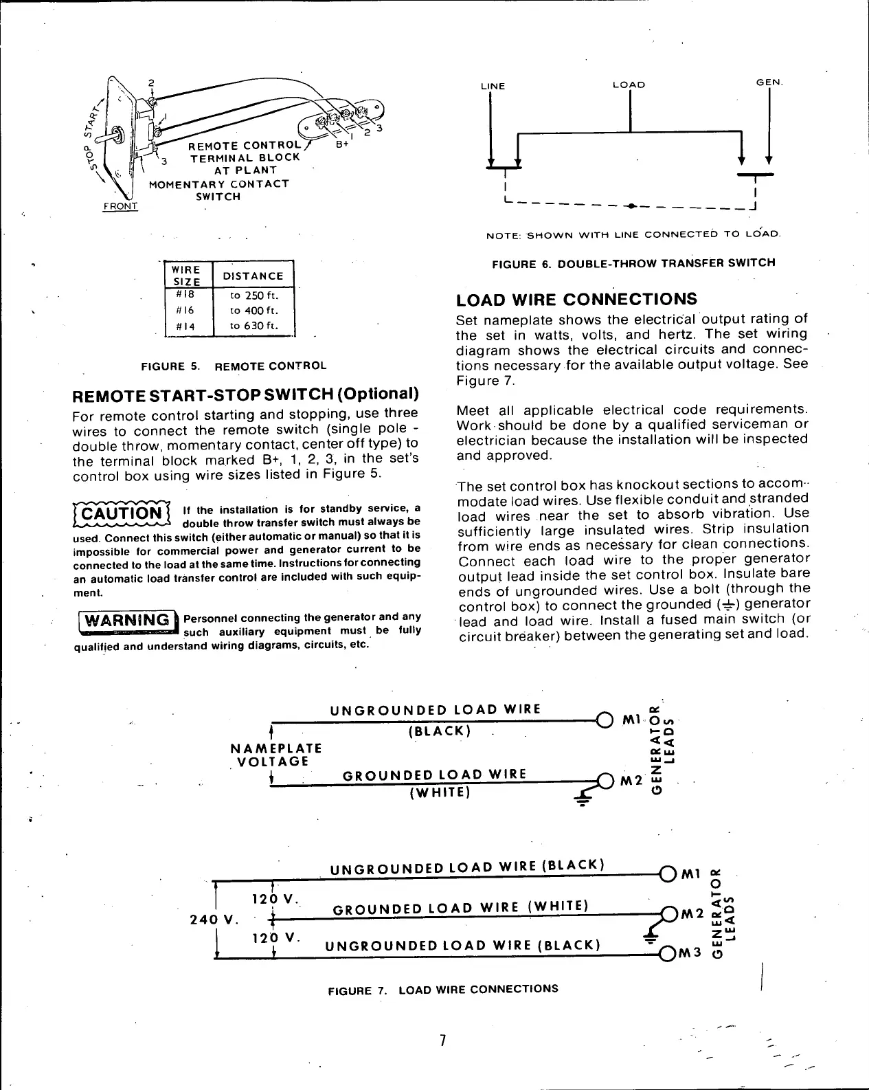
WIRE
SIZE
DISTANCE
#18
to 250 ft.
n 16
to 400 ft.
#14
to 630 ft.
FIGURE 5. REMOTE CONTROL
REMOTE
START-STOP
SWITCH (Optional)
For remote control starting and stopping, use three
wires to connect the remote switch (single pole -
double throw, momentary contact, center off type) to
the terminal block marked B+, 1, 2, 3, in the set's
control box using wire sizes listed in Figure 5.
If the installation is for standby service, a
double throw transfer switch must always be
used.
Connect this switch (either automatic or manual) so that it is
impossible for commercial power and generator current to be
connected to the load at the same time. Instructions for connecting
an automatic load transfer control are included with such equip-
ment.
WARNING \ Personnel connecting the generator and any
HI
MMI
mi ii 11 such auxiliary equipment must be fully
qualified and understand wiring diagrams, circuits, etc.
NOTE:
SHOWN WITH LINE CONNECTED TO LOAD.
FIGURE 6. DOUBLE-THROW TRANSFER SWITCH
LOAD
WIRE CONNECTIONS
Set nameplate shows the electrical output rating of
the set in watts, volts, and hertz. The set wiring
diagram shows the electrical circuits and connec-
tions necessary for the available output voltage. See
Figure 7.
Meet all applicable electrical code requirements.
Work should be done by a qualified serviceman or
electrician because the installation will be inspected
and approved.
The set control box has knockout sections to accom -
modate load wires. Use flexible conduit and stranded
load wires near the set to absorb vibration. Use
sufficiently large insulated wires. Strip insulation
from wire ends as necessary for clean connections.
Connect each load wire to the proper generator
output lead inside the set control box. Insulate bare
ends of ungrounded wires. Use a bolt (through the
control box) to connect the grounded (^r) generator
lead and load wire. Install a fused main switch (or
circuit breaker) between the generating set and
load.
UNGROUNDED
LOAD
WIRE
NAMEPLATE
VOLTAGE
i
(BLACK)
GROUNDED
LOAD
WIRE
(WHITE)
-O
NM O
co
i-o
<<
OC
LAJ
"Z
0
N\2
O
240 V.
T
UNGROUNDED
LOAD
WIRE
(BLACK)
GROUNDED
LOAD
WIRE (WHITE)
120 V.
' f-
12
°
V
" UNGROUNDED
LOAD
WIRE
(BLACK)
FIGURE 7. LOAD WIRE CONNECTIONS
--^OM2
 Loading...


