Governor
System
The purpose of the engine governor
is
to maintain a
constant engine speed during changes in power
demands.
A
governor responds to changes in power
demands by varying the throttle position.
A
constant-
speed governor is standard on marine engines.
GOVERNORS
The constant-speed governor maintains enginespeed
up to
2400
rpm. The speed-sensing device is a ball
and cup mechanism on the camshaft gear. A yoke,
resting on the cup, is connected to the throttle lever.
Any change in engine speed is transmitted from the
cup to the yoke, and on to the throttle.
Tension on thegovernor spring determines thespeed
at which the engine is controlled. Astud screwed into
thespring isused tovarythenumberofeffectivecoils
for getting the desired sensitivity-the speed drop
from no-load to full-load.
Maintenance
Periodically lubricate the metal governor Iinkagewith
lubricating graphite or light non-gumming oil. Also,
inspect the governor linkage for binding or excessive
slack or wear. Plastic ball joint socket does not need
lubrication.
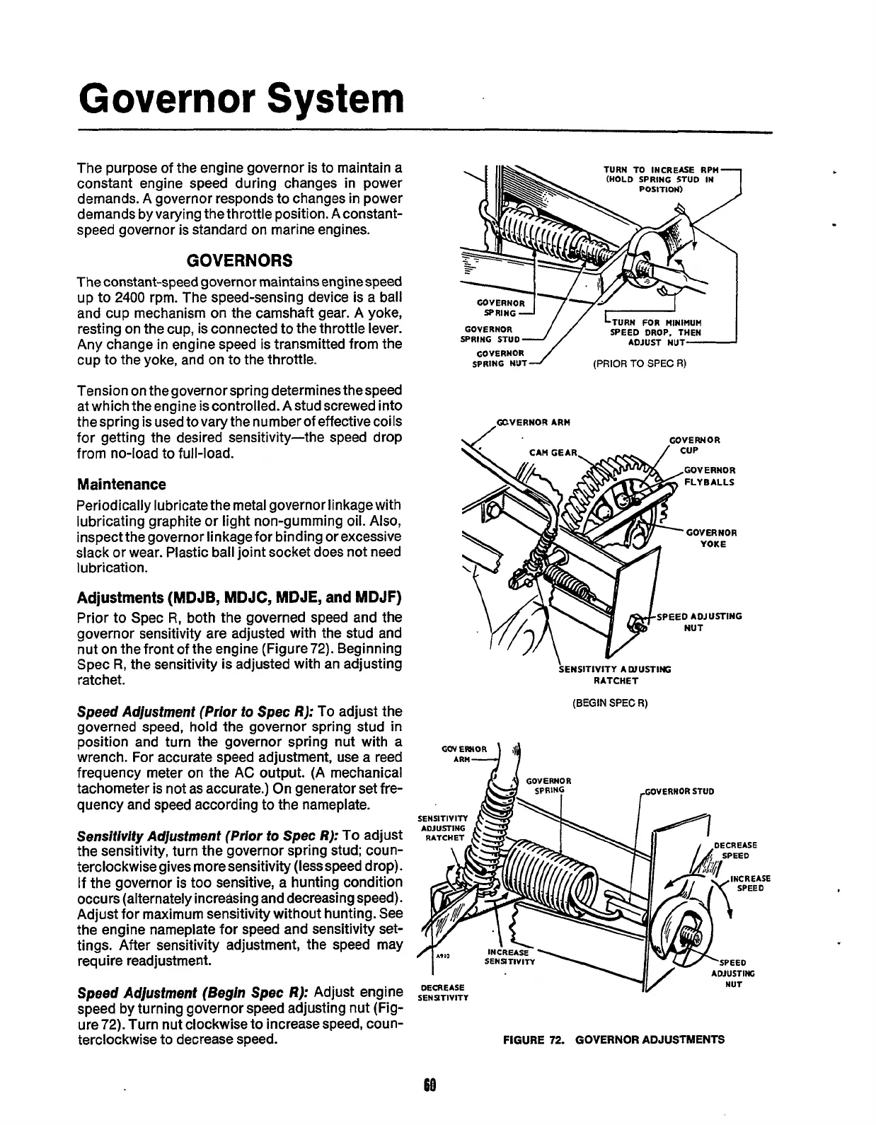
Adjustments (MDJB, MDJC, MDJE, and MDJF)
Prior to Spec
R,
both the governed speed and the
governor sensitivity are adjusted with the stud and
nut on the front of the engine (Figure72). Beginning
Spec
R,
the sensitivity is adjusted with an adjusting
ratchet.
Speed Adjustment
(Prior
to
Spec
R):
To
adjust the
governed speed, hold
the
governor spring stud in
position and turn the governor spring nut with a
wrench. For accurate speed adjustment, use a reed
frequency meter on the
AC
output.
(A
mechanical
tachometer is not as accurate.) On generator set fre-
quency and speed according to the nameplate.
Sensiflvity
Adjustment
(Prior
to
Spec
R):
To
adjust
the sensitivity, turn the governor spring stud; coun-
terclockwise gives more sensitivity (lessspeed drop).
If
the governor is too sensitive, a hunting condition
occurs (alternately increasing and decreasing speed).
Adjust for maximum sensitivity without hunting. See
the engine nameplate for speed and sensitivity set-
tings. After sensitivity adjustment, the speed may
require readjustment.
Speed
Adjustment (Begln
Spec
R):
Adjust engine
speed by turning governor speed adjusting nut (Fig-
ure
72).
Turn nut clockwise to increase speed, coun-
terclockwise to decrease speed.
TURN
TO
INCREASE RPM
(HOLD SPRING
STUD
IN
LTURN
FOR
MINIMUM
SPEED DROP. THEN
ADJUST
NUT-
GOVERNOR-
J/
SPRING
STUD
GOVERNOR
1
SPRING
NUT
(PRIOR
TO
SPEC
R)
GUVERNORARH
\/
’
GOVERNOR
GOVERNOR
YOKE
PEED ADJUSTING
NUT
SENSITIVITY
A
CUUSTlffi
RATCHET
(BEGIN
SPEC
R)
ARM
9
GOVERHOR
STUD
SENSTIVITY
FIGURE
72.
GOVERNOR ADJUSTMENTS
Redistribution or publication of this document,
by any means, is strictly prohibited.
 Loading...


