Oil
System
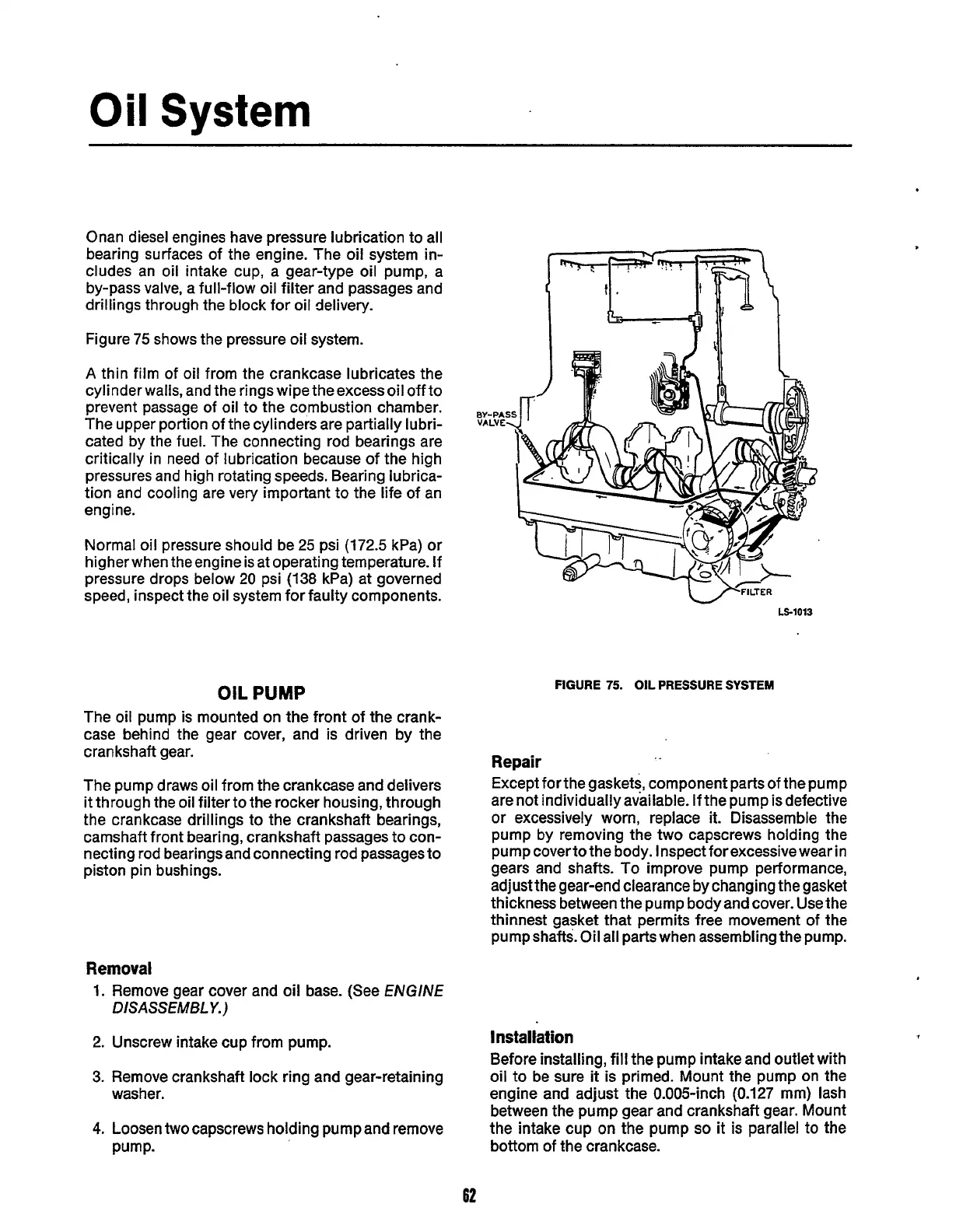
Onan diesel engines have pressure lubrication to all
bearing surfaces of the engine. The oil system in-
cludes an oil intake cup, a gear-type oil pump, a
by-pass valve, a full-flow oil filter and passages and
drillings through the block for oil delivery.
Figure
75
shows the pressure oil system.
A
thin film of oil from the crankcase lubricates the
cylinder walls, and the rings wipe the excess oil off to
prevent passage of oil to the combustion chamber.
The upper portion of the cylinders are partially lubri-
cated by the fuel. The connecting rod bearings are
critically in need of lubrication because of the high
pressures and high rotating speeds. Bearing lubrica-
tion and cooling are very important to the life
of
an
engine.
Normal oil pressure should be
25
psi
(172.5
kPa) or
higher when the engine is at operating temperature. If
pressure drops below
20
psi
(138
kPa) at governed
speed, inspect the oil system for faulty components.
OIL
PUMP
The oil pump is mounted on the front of the crank-
case behind the gear cover, and is driven by the
crankshaft gear.
The pump draws oil from the crankcase and delivers
it through the oil filter to the rocker housing, through
the crankcase drillings to the crankshaft bearings,
camshaft front bearing, crankshaft passages to con-
necting rod bearings and connecting rod passages to
piston pin bushings.
c
-FILTER
LS-1013
FIGURE
75.
OIL
PRESSURE
SYSTEM
Repair
Except for the gaskets, component parts of the pump
are not individually available.
If
the pump is defective
or excessively worn, replace it. Disassemble the
pump by removing the two capscrews holding the
pump coverto the body. Inspect forexcessive wear in
gears and shafts. To improve pump performance,
adjust the gear-end clearance by changing the gasket
thickness between the pump body and cover. Use the
thinnest gasket
that
permits free movement of
the
pumpshafts. Oil all parts when assembling the pump.
Removal
1.
Remove gear cover and oil base. (See
ENGINE
2.
Unscrew intake cup from pump.
3.
Remove crankshaft lock ring and gear-retaining
4.
Loosen
two
capscrews holding pump and remove
DISASSEMBLY.)
Installation
Before installing, fill the pump intake and outlet with
oil to be sure
it
is primed. Mount the pump on
the
engine and adjust the 0.005-inch
(0.127
mm) lash
between the pump gear and crankshaft gear. Mount
the intake cup
on
the pump
so
it
is
parallel to the
washer.
Pump-
bottom
of the crankcase.
62
Redistribution or publication of this document,
by any means, is strictly prohibited.
 Loading...


