12
2. Mounting the Sprinkler Timer
• Use the mounting template (included) to mark the screw
locations on the wall.
• Insert a No. 8 screw (included) in the upper mark, leaving
the screw head about 1/8” (3mm) out from the wall. (Use the
expanding anchors in plaster or masonry if necessary.)
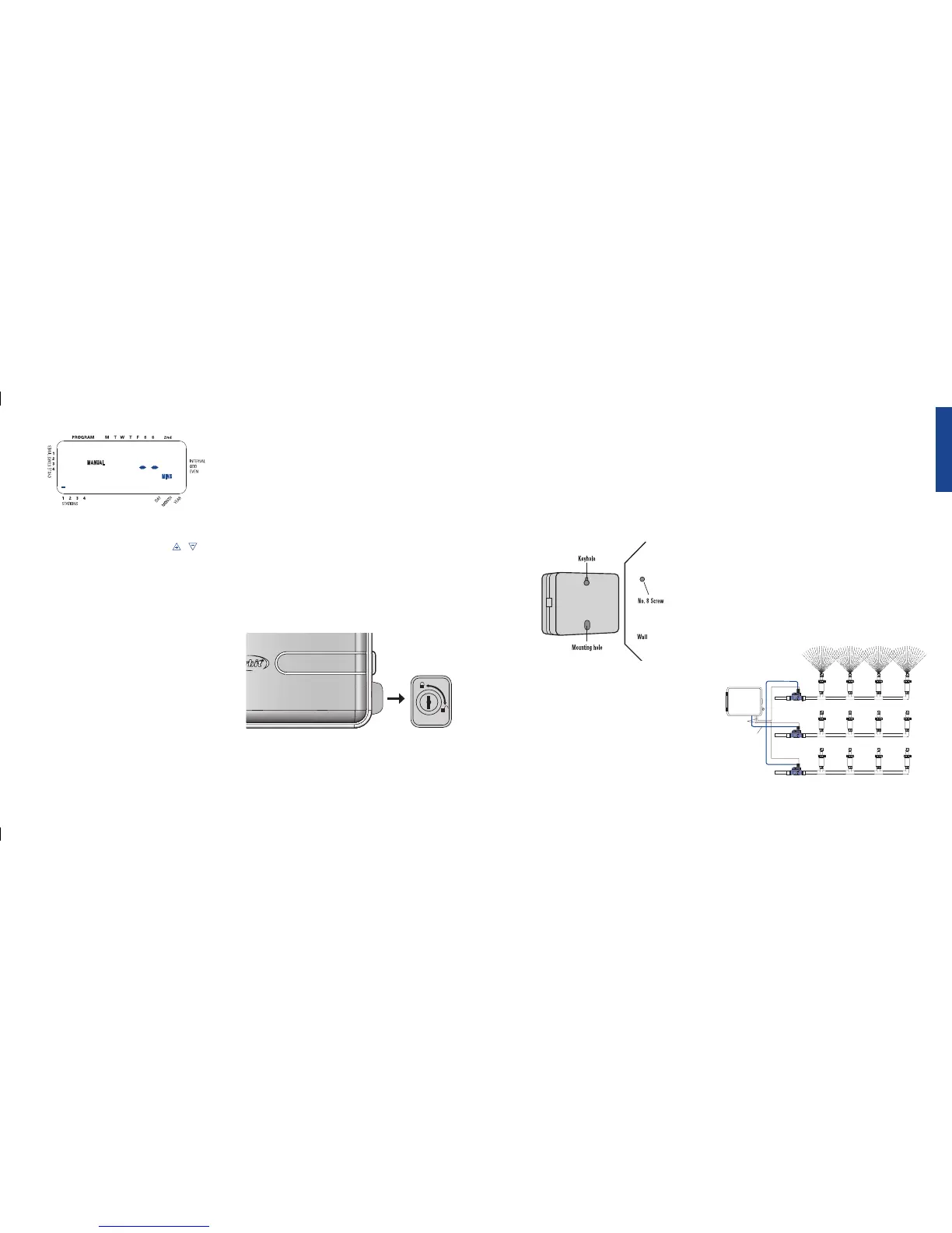
• Slip the keyhole slot in the back of the sprinkler timer over the
extended screw. [See Figure 12b]
• Screw a No. 8 screw through the hole located behind the wire
shroud cover.
3. Install the Batteries
One Lithium battery (CR2032) is required to retain the program in
memory during power loss. Annual replacement is recommended.
• See page 3 for battery replacement
Note: The battery alone will not operate the valves in your sprinkling
system. The sprinkler timer has a build-in transformer that must be con-
nected to an AC line voltage source.
4. Wiring the Electric Valves
Note: If the distance between the sprinkler timer and valves is under 700’
(210 m), use Orbit
®
sprinkler wire or 20 gauge (AWG) plastic jacketed
thermostat wire to connect the sprinkler timer to the valves. If the distance
is over 700’ (210 m), use 16 gauge (AWG) wire.
• Taking the sprinkler wire, strip 1/2” (12 mm) of the plastic
insulation off the end of each individual wire.
• Connect one wire from each valve (it doesn’t matter which
wire) to a single “Common” sprinkler wire (usually white)
[See Figure 13]
Important: All wires should be joined together using wire nuts, solder,
and/or vinyl tape. For additional protection to waterproof connections,
an Orbit
®
grease cap can be used.
• Next connect the remaining wire from each valve to a separate
colored sprinkler wire.
• To avoid electrical hazards, only one valve should be connected
to each station.
Important: The wire can be buried in the ground; however, for more
protection wires can be pulled through PVC pipe and buried underground.
Be careful to avoid burying the wires in locations where they could be
damaged by digging or trenching in the future.
Figure 13: Connecting Sprinkler Wires to Valves
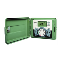
advance to watering for station 3; using the or key, set
the manual watering duration to five minutes; press ENTER).
Note: After the MANUAL key has been pushed, if a selection is not made
within 60 seconds the display returns to the time of day.
• To halt or discontinue manual watering, press the CLEAR key
once. The timer will revert to your original automatic watering
schedule.
Section 6: Sprinkler Timer Installation
Before installation please have the following items and tools.
• Phillips Screwdriver
• Wire Strippers
Installing the sprinkler timer in 5 easy steps
1. Selecting a Location
2. Mounting the Sprinkler Timer
3. Activating the Battery
4. Connecting Valve Wires to Sprinkler Timer
5. Connecting Electrical Power
1. Selecting a Location
Select a location with the following criteria:
• Near a power source (if hard wiring) or electrical outlet (appli-
cable only to U.S. retail timers)
• A location, where operating temperatures are not below 32° or
above 158° Fahrenheit (0 degrees or above 70 degrees Celsius
• A location, with at least 9” of space to the left of the sprinkler
timer box for the door to swing open after installation
Note: Sprinkler timers are weather-resistant to UL-50 and ETL
®
Listings, but should not be placed in areas where continuous water
could cause damage.
• A location without direct sunlight
• Access to sprinkler wire (from valves)
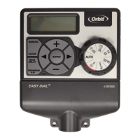
Caution: Do not open the Sprinkler Timer when it is raining.
If mounted in an outdoor location, shut the compartment door to
keep the timer safe from weather damage. To lock: insert the key
and turn counterclockwise to the locked position.
Figure 11: Manually Running Individual Stations
ENGLISH
Figure 12b: Mounting the Sprinkler Timer
13
Figure 12a
 Loading...