14
• To avoid electrical hazards, only one valve should be
connected to each station.
IMPORTANT: The wire can be buried in the ground. However,
for greater protection, wires can be pulled through PVC pipe
and buried underground. Be careful to avoid burying the wires
in locations where they could be damaged by future digging or
trenching.
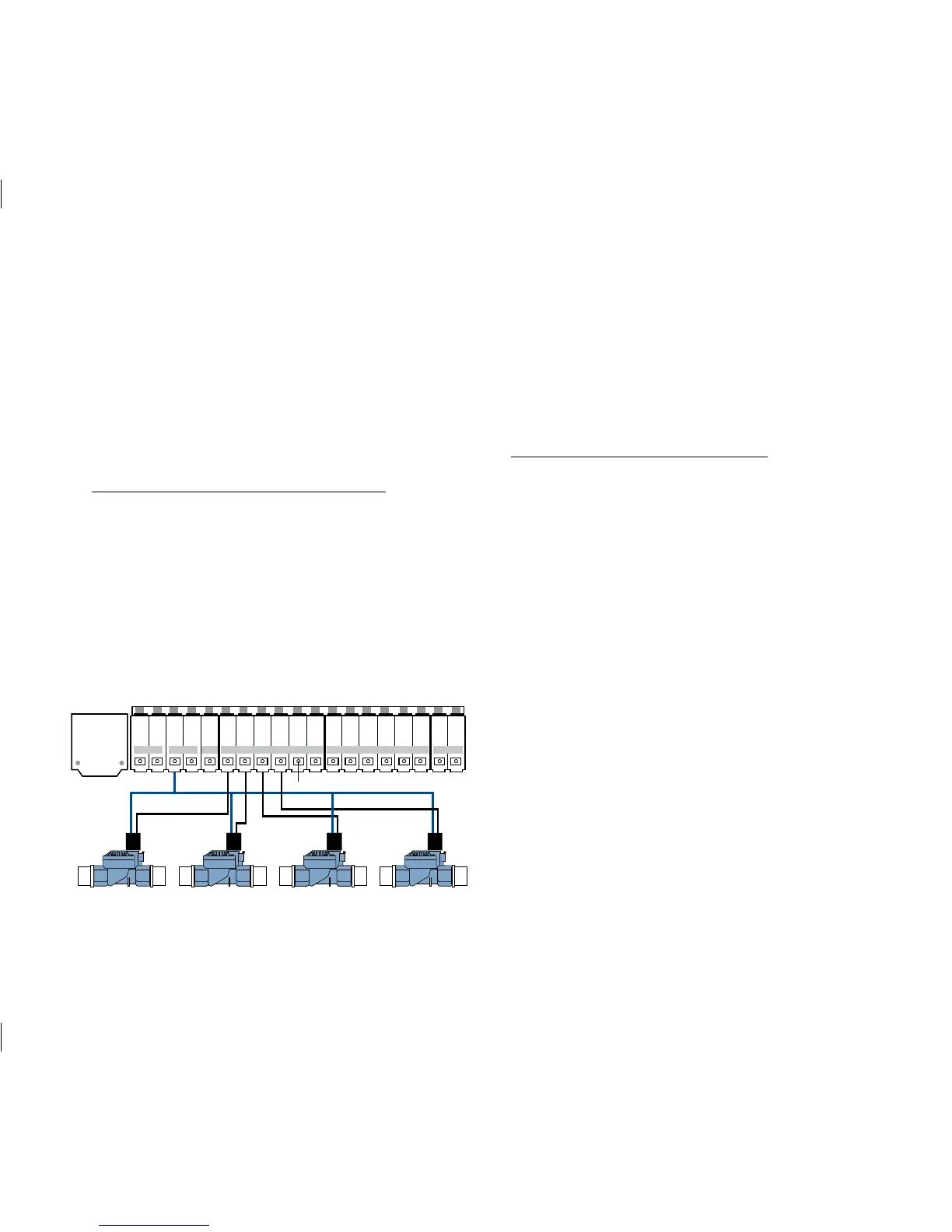
B. Connect Valve Wires to the Sprinkler Timer
• Strip 1/4" (6 mm) of the plastic insulation off the end
of each wire.
• Determine which valve you want to connect to which
station. Insert each sprinkler wire, excluding the
“common” wire, into a separate station socket (num-
bered above each socket) by inserting the bare wire
fully into the socket under each number. (See Figure 5)
• Connect the common wire to one of the two sockets
(white in color) labeled “COM.”
NOTE: Insert only one wire into each “COM” socket. If more
than two common wires are required, splice several together so
only one wire runs into each of the two “COM” terminals. Protect
the splice connection with a wire nut.
C. Connect Pump Start and Master Valve
This timer allows a master valve or pump start relay to oper-
ate whenever a station is on.
NOTE: If you are activating a pump from this timer, you must
purchase a Pump Start Relay.
From the pump start relay (or master valve); connect one
wire to the “PUMP” socket and the other wire to the “COM”
socket.
Once all connections to the docking port are made, you may
slide the timer back onto the docking port.
5. Mount the Sleeve for the Remote Control Device
• Using the mounting template (included) mark the two
screw locations on the wall, then drill holes at the marks
for No. 8 screws. Use the expanding anchors in plaster or
masonry if necessary. (The sleeve can be mounted any
where and does not need to be next to the timer.)
• Place the remote control device sleeve against the wall,
aligning the two holes in the sleeve with the two
drilled holes.

 Loading...