7
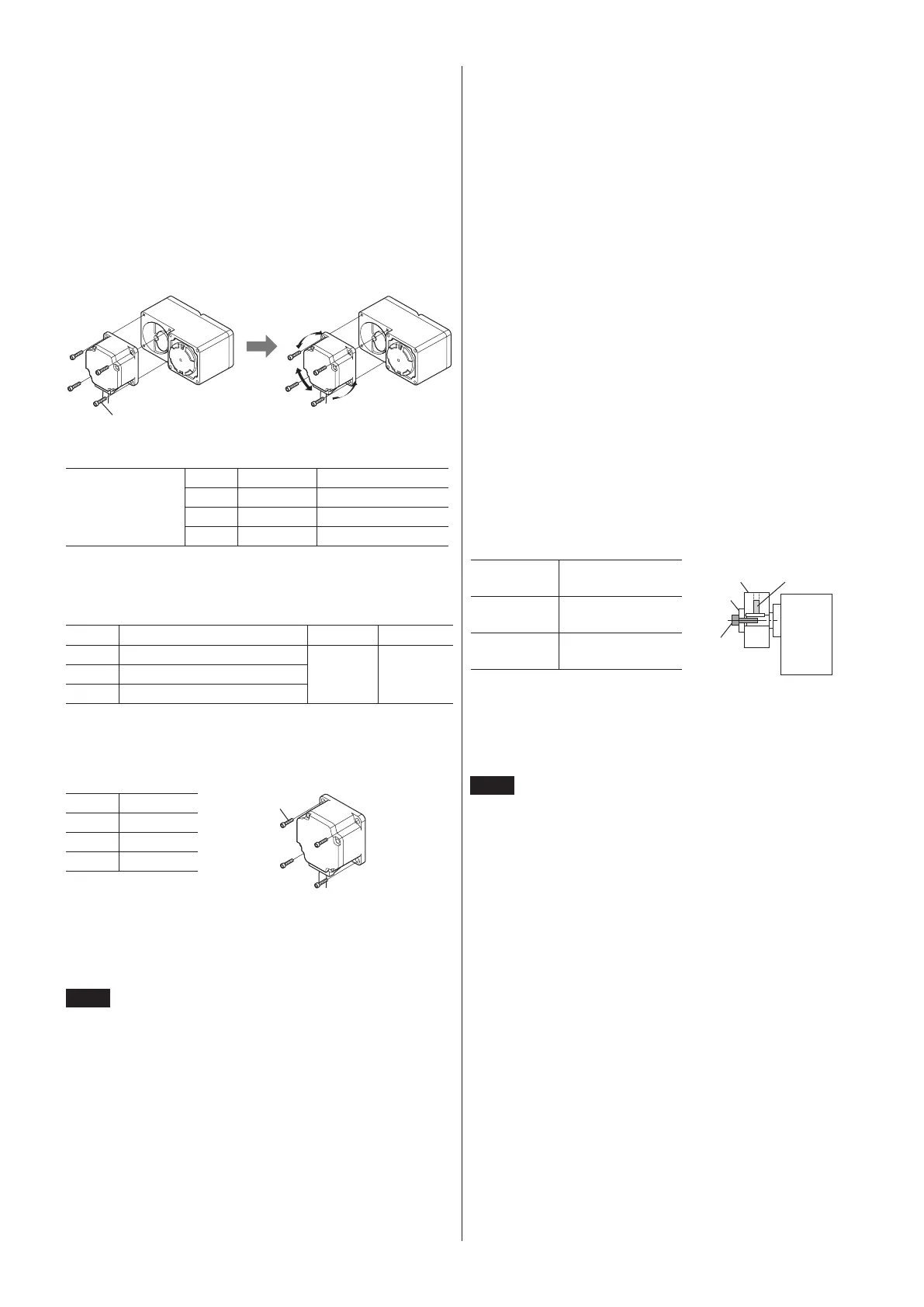
Removing/Installing the gearhead
To replace the gearhead or change the cable outlet direction, remove the
screws assembling the gearhead. The gearhead can be removed and the motor
cable position changed to one of three 90° directions. Note that the motor
cable cannot be positioned in the direction where the cable faces the gearhead
output shaft.
1. Remove the hexagonal socket head screws (4 pcs) attaching the motor and
gearhead and detach the motor from the gearhead.
2. Using the pilot sections of the motor and gearhead as guides, install the
motor to the gearhead and tighten the hexagonal socket head screws.
Install the motor carefully to prevent the pinion of the motor output shaft
from contacting the casing or gear of the gearhead.
Hexagonal socket
Change the cable
position to a desired
90° direction.
Assembly screws
Model Screw size Tightening torque
BLE23
M4 1.8 N·m (15.9 lb-in)
BLE46
M6 6.4 N·m (56 lb-in)
BLE512
M8 15.5 N·m (137 lb-in)
Installing the round shaft type
Install the motor to a mounting plate of the following size or larger, so that
the motor case temperature will not exceed 90 °C (194 °F).
Model Size of mounting plate Thickness Material
BLE23
115×115 mm (4.53×4.53 in.)
*
5 mm
(0.20 in.)
Aluminum
alloy
BLE46
135×135 mm (5.31×5.31 in.)
BLE512
165×165 mm (6.50×6.50 in.)
∗*
Electromagnetic brake type: 135×135 mm (5.31×5.31 in.)
Secure the motor using the hexagonal socket head screws (not supplied)
through the four mounting holes. Tighten the nuts until no gaps remain
between the motor and mounting plate.
Model Screw size
BLE23
M4
BLE46
M6
BLE512
M8
Installing a load to the combination type • parallel
gearhead or round shaft type
When installing a load on the motor, gearhead, align the center of the motor
output shaft (gearhead output shaft) with the center of the load shaft.
Note
•
When coupling the motor, gearhead with a load, pay
attention to centering, belt tension, parallelism of pulleys,
etc. Also, rmly secure the tightening screws of the coupling
or pulleys.
•
When installing a load, do not damage the motor output
shaft (gearhead output shaft) or bearing. Forcing in the load
by driving it with a hammer, etc., may break the bearing. Do
not apply any excessive force to the output shaft.
•
Do not modify or machine the motor, gearhead output shaft.
The bearing may be damaged or motor, gearhead may
break.
•z
Output shaft shape
Combination type • parallel shaft gearhead
A key slot is provided on the output shaft of each combination type parallel
shaft gearhead. Form a key slot on the load side and secure the load using the
supplied parallel key.
Round shaft type
A at section is provided on the motor output shaft of each round shaft type.
Apply a double-point screw, etc., at the at section to rmly secure the load
and prevent it from spinning.
•z
How to install a load
Using a coupling
Align the centerline of the motor, gearhead output shaft with the centerline of
the load shaft.
Using a belt drive
Adjust the motor, gearhead output shaft to lie parallel with the load shaft and
form right angles between the output shaft/load shaft and the line connecting
the centers of both pulleys.
Using a gear drive
Adjust the motor, gearhead output shaft to lie parallel with the gear shaft and
allow the output shaft to mesh correctly with the centers of the gear teeth.
When using the output shaft end tapped hole of a gearhead
Use a tapped hole provided at the end of the output shaft as an auxiliary
means for preventing the transfer mechanism from disengaging.
(The output shaft end tapped hole is not provided for the
GFS2G
type.)
Gearhead
model name
Output shaft end
tapped hole
Screw
parts
GFS4G
M5, Eective depth
10 mm (0.39 in.)
GFS5G
M6, Eective depth
12 mm (0.47 in.)
Installing a load to the combination type • hollow shaft
at gearhead
If the motor is subject to a strong impact upon instantaneous stop or receives
a large radial load, use a stepped load shaft.
Note
•
Apply grease (molybdenum disulde grease, etc.) on the
surface of the load shaft and inner walls of the hollow output
shaft to prevent seizure.
•
When installing a load, do not damage the hollow output
shaft or bearing of the gearhead. Forcing in the load by
driving it with a hammer, etc. may break the bearing. Do not
apply any excessive force to the hollow output shaft.
•
Do not modify or machine the hollow output shaft of the
gearhead. Doing so may damage the bearings and destroy
the gearhead.
 Loading...
