6 | GSG-8 Getting Started Guide orolia.com
Hardware Parts:
1 or 2 PNY Nvidia Quatro RTX 5000
Orolia CDM-5 with on-board OCXO. Accuracy < 100 ppb
Orolia CDM-5 Information:
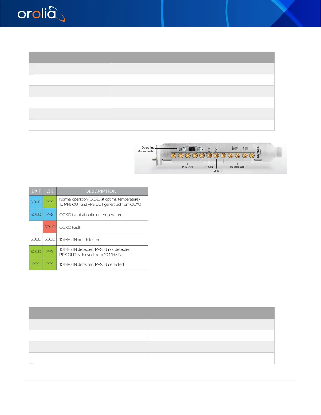
The GSG-8 contains an Orolia CDM-5 to
distribute a 10 MHz reference clock and
1PPS signals throughout the integrated
SDRs. The CDM-5 is added to your GSG-8
to create a maintenance-free timing mechanism. If necessary, it also contains 2 LED indicator lights to
provide information about the current oscillator validity.
(See chart below). The CDM-5 has an Operating Modes
switch (INT or EXT).
To use the CDM-5 as the simulator’s reference clock, the
operating modes switch must be set to INT. This is the
default setting and will be preconfigured on your GSG-8.
To use the CDM-5 to provide the 10 MHz and PPS
signals of an external reference to the simulator, you
must turn the Operating Modes switch to EXT, connect
your 10 MHz reference clock to the CLK connector of
the CDM-5, and connect your 1PPS source signal to the
PPS IN connector of the CDM-5.
Software:
CDM-5 LED indicator lights
*PPS indicates LED is flashing at 1 pulse-per-second. A 4-second
alternating color pattern occurs during normal boot sequence.
 Loading...