Installing the indoor unit
20
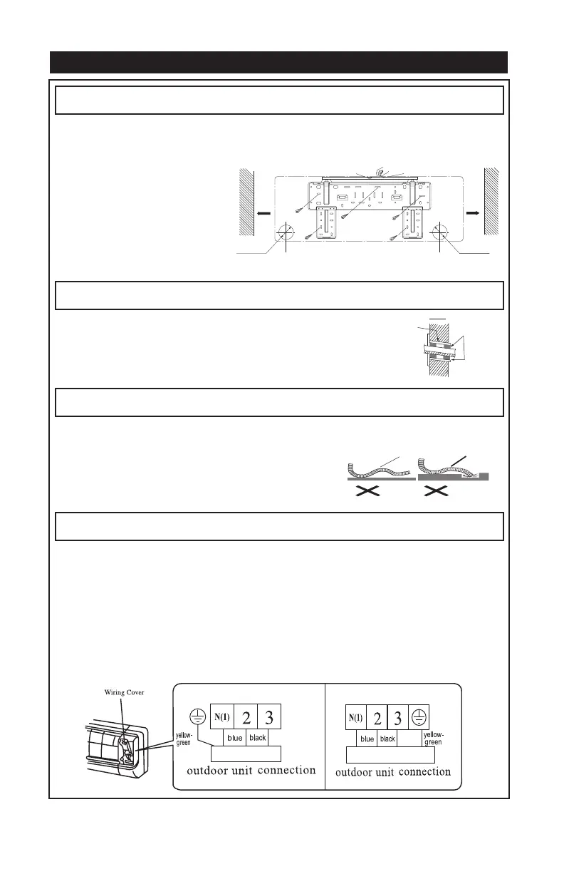
Install the Rear Panel
1. Always mount the rear panel horizontally. As the water drainage pipe is on the left, when adjusting the
rear panel, this side should not be too high; the right side should be slightly higher.
2. Attach the rear panel to the selected
location.
3. Be sure that the rear panel has been
attached firmly enough to withstand
the 60 kg of weight. The weight
should be evenly shared by each
screw.
e pipe
Fig.1
e pipe
Fig.1
Wall
Left
Right
Rear pipping holeRear pipping hole
Mark on the middle of it
Gradienter
Wall
Space to
the wall
150mm
above
Space to
the wall
150mm
above
Install the Piping Hole
Install the Water Drainage Pipe
Connect indoor and outdoor electric wires
1. Make the piping hole in the wall at a slight downward slant to the
outdoor side
2. Insert the piping-hole sleeve into the hole to prevent the connection
piping and wiring from being damaged when passing through the hole.
1. To ensure good drainage, the drain hose should be
placed at a downward angle.
2. Do not wrench or bend the drain hose or it will flood.
3
. When the long drainage hose passe through the indoor
section, the insulation materials should be wrapped.
1. Lift the front panel up.
2. Unscrew off the fixing screw in the cover plate and remove the cover plate Fig.6.
3. Put the power connection cable through the back of indoor unit wire hole and pull it through..
4. All the wiring should be connected according to the circuit diagram on the unit.
5
. Place the power connection cable into the wire groove, cover with the sheath and then the cover plate.
Screw in the fixing screw and tighten the connection wire.
6. Cover the front panel cover.
7. For the cooling and heating unit, the signal control wire can be passed through the indoor unit
connection. Use the wire clip that is under the body case, tighten the signal control wire.
Installation de unité intérieure
20
Installer le panneau arrière
1. Fixez toujours le panneau arrière à l’horizontale. Puisque le tuyau de drainage de l’eau se trouve à
gauche, le panneau arrière ne devrait pas être fixé trop haut. Le côté droit devrait être légèrement surélevé.
2. Fixez le panneau arrière à l’endroit
désiré.
3. Assurez-vous que le panneau arrière
soit bien en place afin qu’il puisse
supporter 60 kg (132 lb) de poids. Le
poids devrait être réparti également
pour chacune des vis.
e pipe
Fig.1
e pipe
Fig.1
Mur
Gauche
55mm 55mm
Droite
(trou pour les tuyaux
à l’arrière)
(trou pour les tuyaux
à l’arrière)
Indoor
Wrenched Bent
Flooded
Tordu Plié
Débordement
Wall pipe
Seal pad
Outdoor
Intérieur
Tuyaux
dans le mur
Coussin
d’étanchéité
Extérieur
ø55
Marque au milieu
Gradateur
Mur
150mm
d’espace
par
rapport
au mur
150mm
d’espace
par
rapport
au mur
Percer le trou pour les tuyaux
Installer le tuyau de drainage de l’eau
Raccorder les fils électriques à l’intérieur et à l’extérieur
1. Percez un trou dans le mur pour les tuyaux, avec une légère inclinaison
vers l’extérieur.
2. Insérez dans le trou le manchon à cette fin pour ne pas endommager le
tuyau et le fil de raccordement lorsqu’ils passeront dans le trou.
1. Pour faciliter le drainage, le tuyau devrait être
légèrement incliné.
2. Ne tordez ou ne pliez pas le tuyau de d
rainage,
car il débordera.
3. Lorsque le long tuyau de drainage passe à l’intérieur,
il devrait être revêtu de matériaux isolants.
1. Soulevez le panneau avant.
2. Dévissez les vis de fixation du panneau de revêtement et retirez ce dernier Fig 6.
3. Insérez les fils électriques dans le trou pour les tuyaux de l’appareil interne situé à l’arrière et tirez
sur les fils.
4. Tous les fils devraient être ra
ccordés selon le diagramme du circuit situé sur l’appareil.
5. Remettez le panneau de revêtement en place à l’aide des vis de fixation.
6. Rabaissez le panneau avant.
7. Pour les appareils de refroidissement et de chauffage, le fil de commande des signaux peut être
inséré dans l’appareil interne. Utilisez l’agrafe située sous le boîtier. Serrez le fil de commande des
signaux.
Fig.
6
brown
brown
for 18K 、24K models 18、24K
(for some models)
Fig.
6
brown
brown
for 18K 、24K models 18、24K
(for some models)
pour modèles 18K 24K
unité de connection extérieur
unité de connection extérieur
pour modèles 18K 24K
Couvert de fillage
Couvert de fillage
Jaune
Vert
Jaune
Vert
bleu
noir
brunbleu
noir
brun
ø55
55mm 55mm
00687_Unité_de_Climatisation_Murale_Ouellet_Climatiseur Mobile8.5x11 An+FR 15-08-13 13:51 Page21
 Loading...