MPC2000D Issue 2 22/4/98 Page 37
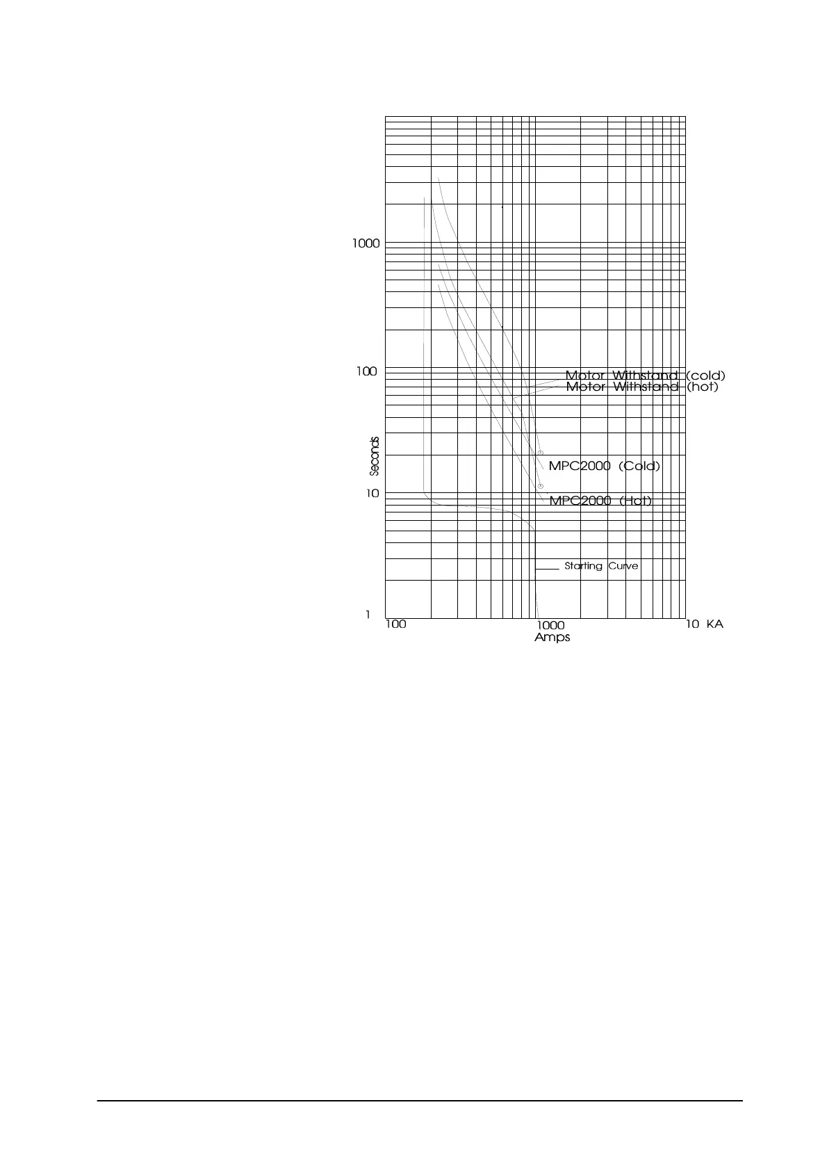
The curves shown on the right are the
actual curves for the calculated figures
and show that the setting has been chosen
to provide close protection to take
advantage of the motors capability and
allow the possibility of an immediate
restart from the Hot condition. However
alternative settings can be made to provide
faster tripping limited by the conditions of
ensuring the motor can run up speed under
healthy conditions without tripping.
If the Hot to Cold ratio is set to a figure
other than the 3 standard curves drawn,
then either the formula quoted below can
be used or an approximation of the Hot
curve can be drawn to calculate trip times.
(Starting/Cold Condition)
t
c
= 32.a.log
e
( p
2
)
--------
p
2
- s
2
where 'p' is multiple of motor FLC (per
unit value)
's' is overload setting in per unit
value e.g. 105%
'a' is setting of t6x in seconds
't
c
is the operating time in
seconds
(Running/Pre-load Condition)
t
c
= 32.a.log
e
( p
2
- (1-H/C)(I
L
)
2
)
--------------------
p
2
- s
2
Where 'I
L'
is the steady state load prior to overload condition divided by motor FLC, e.g. if motor is running at FLC,
I
L
=1.
'H/C' is the hot/cold ratio in per unit value e.g. 40% hot to cold ratio = 0.40.
The Cool Time Factor is factory set at 5 unless specific information is available from the motor manufacturer to
calculate the actual setting it is recommended that the default setting is used.
With regard to current unbalance protection the pick up default setting is 15% and trip time is 30 seconds. These
figures should be set to the motor requirements if the Negative Phase Sequence withstand can be obtained. Formula
for calculating the unbalance setting can be obtained from P & B Engineering on request.
Further help on the application of thermal overload protection by ringing P & B Engineering at Manchester on 0161
230 6363.
 Loading...