MPC2000D Issue 2 22/4/98 Page 39
16.2 MPC2000D Terminations
All terminations to the MPC2000D are situated to the rear of the unit, and are suitable for use with standard crimped
connectors.
The rear terminal block accepts both pre-insulated screw and push-on blade type connectors. Each terminal has 1
screw type and 2 blade type connectors.
Screw: Each connection uses a 4mm (M4) screw outlet and accepts standard L-shaped ring
type connectors designed for 4mm screws.
Blade: Each connection facilitates 2 pre-insulated push-on blades 4.8mm wide 0.8mm
thick complying with BS5057.
Combinations: Each terminal will accept either;
2 ring type connectors
or 2 push-on blade type connectors
or 1 ring type connector & 1 push-on blade type connector
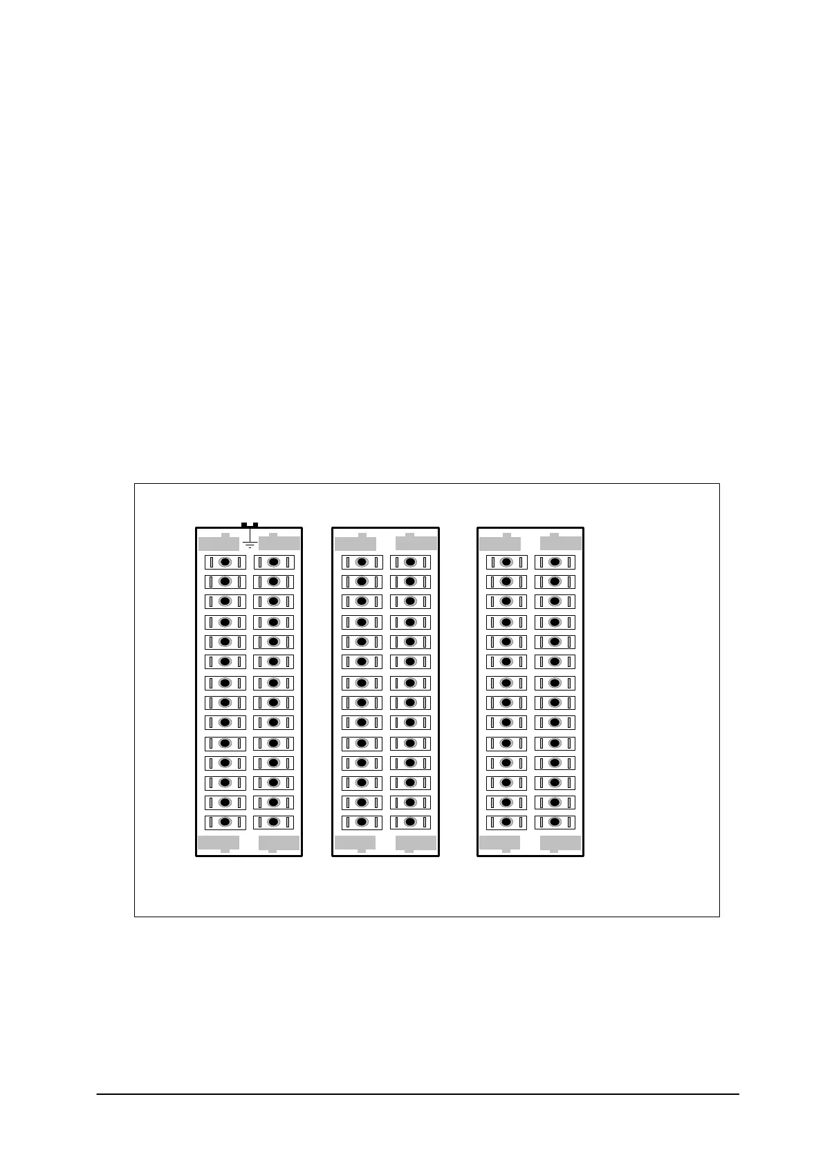
The following diagram shows the position of the terminals.
1
3
5
7
9
11
13
15
17
19
21
23
25
27
2
4
6
8
10
12
14
16
18
20
22
24
26
28
Earth
Rear terminal block connections.
Each terminal
1 screw &
2 spade
29
31
33
35
37
39
41
43
45
47
49
51
53
55
30
32
34
36
38
40
42
44
46
48
50
52
54
56
57
59
61
63
65
67
69
71
73
75
77
79
81
83
58
60
62
64
66
68
70
72
74
76
78
80
82
84
 Loading...