14/1/98 Page 9 Issue H
5.1.3. Fault indication
When the relay has tripped, the display will show "TRIP" and the relevant LED will be illuminated
red. On cycling through the displays in Mode 1, a four letter mnemonic describing the trip will be
displayed. The mnemonics are listed in the table below.
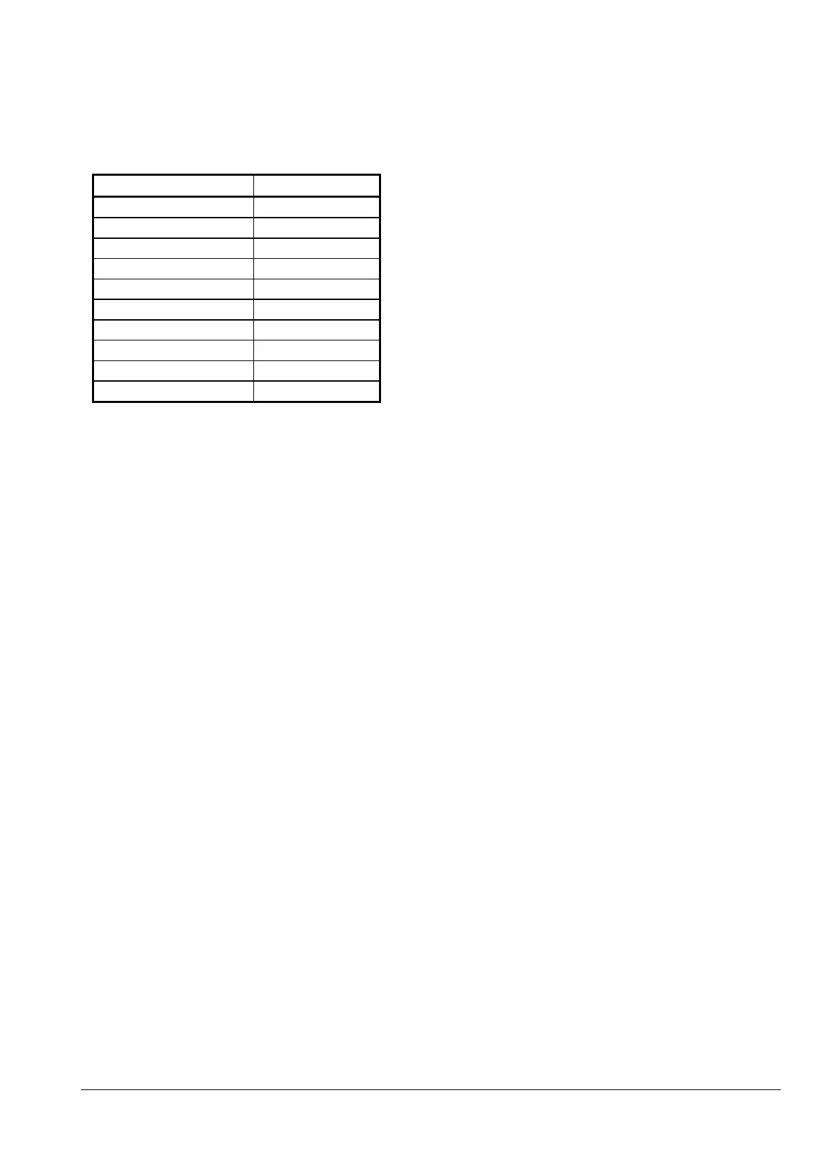
Trip Mnemonic
Overload OVLD
Earth Fault EFLT
High Set Overcurrent HSOC
Low Set Overcurrent LSOC
Unbalance NPSC
Undercurrent UCUR
Too Many Starts STLM
Phase Reversal ROTN
Stalled STLD
Single Phasing SPHA
Should an internal fault occur causing the relay to alarm, then the mnemonic "IRF" followed by a
number will be displayed. If this occurs, or any other indication such as "UDEF" then the
indication/number should be noted and reported to the P&B Engineering office ( +44 161 230 6363).
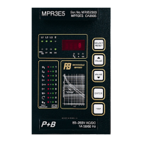
5.2. LED indicators
The LEDs to the left of the display indicate measuring or tripping values. The purpose of the
corresponding LED is identified by the adjacent inscription.
The first row of four LEDs to the left of the display are tri-coloured, green and yellow indicate
measuring and red indicates a fault condition.
The LED marked RS indicates active serial data communication.
The rest of the LEDs are used when accessing Mode 1 and Mode 2 of the Display.
5.3. Push buttons
The front panel contains five push buttons used for setting, measuring and other user functions.
The individual setting and measuring values can be selected in turn by pressing the <SELECT> /
<RESET> push button. This button also resets the relay if pressed for approximately 3 seconds.
The <UP> and <DOWN> push buttons are for incrementing and decrementing any selected
parameter. Continuous pressing of these push buttons will cause the parameter to change at an
increased rate.
The <ENTER> push button is used to transfer the indicated value to the internal parameter memory.
An unintended or unauthorised change of the selected parameter can be avoided through the
password protection facility.
The <TRIP> push button is used to test the output relay circuits, both for tripping and signalling.
This operation is also password protected.
 Loading...