14/1/98 Page 18 Issue H
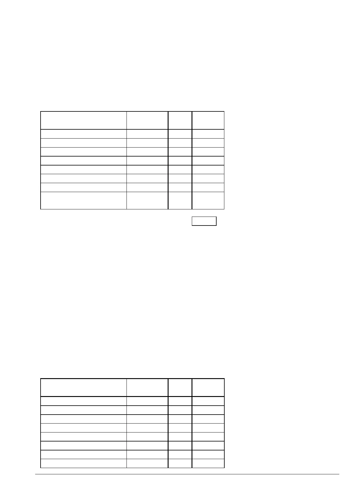
7.4.3 Alarm Relay Matrix, Annn
This setting range, 000 to 255, sets the faults that will cause the Alarm Relay to be either energised
or de-energised upon activating.
Example
Only Thermal Pre-Alarm, Earth Fault Alarm and Low Set Alarm are required and the relay is to de-
energise upon Alarm. Therefore the set value would be: 161
Action Numerical
Value
Set
Y/N
Value
Earth Fault Alarm 128 Y 128
High Set Alarm 64
Low Set Alarm 32 Y 32
NPS Alarm 16
Number of Starts Alarm 8
Undercurrent Alarm 4
Phase Rotation Alarm 2
Relay De-energises on
Alarm
1 Y 1
161
A Thermal Pre-Alarm will always operate i.e. Change the state of, the Alarm Relay.
7.4.4 Earth fault parameters Matrix, Ennn
This setting, range 000 or 129 to 255, sets the Earth Fault source (Core Balance or Residual
connection), and if Core Balance the Primary Rating of the Core Balance CT. It is assumed that the
core balance secondary CT rated current is always 1A.
Example 1-Core balance CT(CBCT):
To configure the relay such that operation is via a Core Balance CT with a primary rating of 1500A,
then the value set would be: 203
If the exact primary rating cannot be selected, for example 50A, then select the next highest standard
above this e.g. 60A. The required primary earth fault setting can then be obtained within the earth
fault parameter range.
Action Numerical
Value
Set
Y/N
Value
Core Balance CT 128 Y 128
1280 64 Y 64
640 32
320 16
160 8 Y 8
80 4
40 2 Y 2
20 1 Y 1
 Loading...