13
Parker Hannifin Corporation
Proportional DC Valves
Series D*FC, D*1FC
Operation Manual
D_FC 5715-686 UK 07.02.2019
• The valve may be mounted fix or movable in
any direction.
• Verify the mounting surface for the valve. Un-
evenness of 0.01 mm /100 mm, surface finish of
6.3 µm are tolerable values.
Keep clean valve mounting surface and work
environment!
• Remove protection plate from the valve mount-
ing surface
• Check the proper position of the valve ports and
the O-rings.
Mounting bolts:
D1FC: 4 pcs. M5x30
D3FC: 4 pcs. M6x40
D31FC: 4 pcs. M6x40
D41FC: 2 pcs. M6x55, 4 pcs. M10x60
D91FC: 6 pcs. M12x75,
D111FC: 6 pcs. M20x90
Use property class 12.9, ISO 4762
Tighten the bolts crisscross with the following
torque values:
Insufficient condition of the valve mounting
surface might create malfunction! Incorrect
mounting resp. bolt torque may result in abrupt
leakage of hydraulic fluid on the valve ports.
Pressure fluids
The following rules apply for the operation with
various pressure fluids: The above information
serves for orientation and does not substitute user
tests among the particular operating conditions.
Particularly no liability for media compatibility may
be derived out of it.
Mineral oil: usable without restrictions
For operation with the following pressure fluids
please consult Parker:
For detailed information concerning pressure fluids
note VDMA-document 24317 as well as DIN 51524
& 51502.
Special gaskets may be available depending
on the utilized fluid. In case of insecurity please
consult Parker.
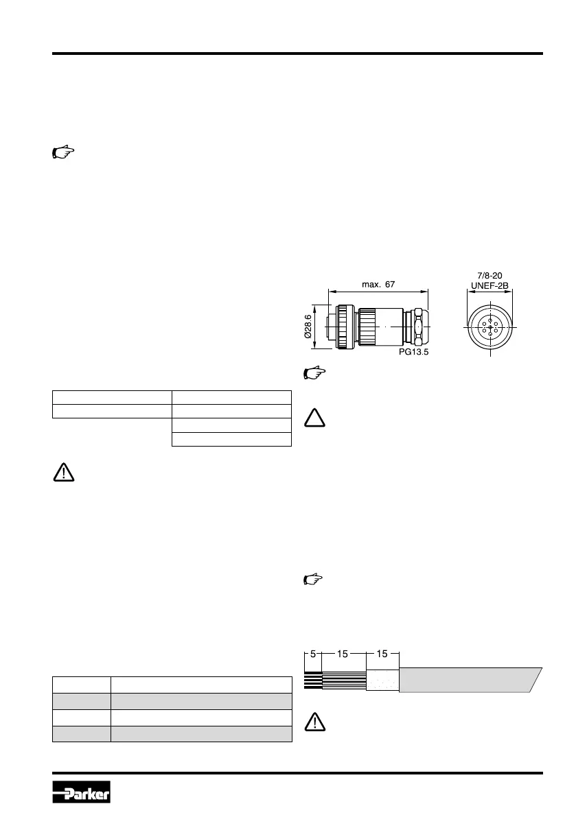
Electrical connection
The electrical connection of the valve takes place
by one common cable, which is coupled to the
integrated electronic driver by a central connector
assembly.
The connection Codes 0 and 7 requires a 6 + PE
female connector EN 175201-804.
HFA Oil-in-water emulsion
HFB Water-in-oil emulsion
HFC Aqueous solution (glycols)
HFD Unhydrous fluids (Phosphor-Ester)
The female connector has to be ordered
separately under article nr. 5004072.
A female connector with metal housing is
required! Plastic made models may create
function problems due to insufficient EMC-
characteristics.
The connecting cable has to comply to the follow-
ing specification:
Cable type control cable, flexible, 7 conduc-
tors, overall braid shield
Cross section min. AWG16/1.0 mm
2
Outer dimension 8...12 mm
Cable length max. 50 m
For cable lengths > 50 m consult Parker.
The connection cable is coupled to the female
connector by solder joints.
Skinning lengths for the connecting cable:
Do not disconnect cable socket under tension!
D1FC: 7.6 Nm D31FC: 13.2 Nm
D3FC: 13.2 Nm D41FC: 13.2/63 Nm
D91FC: 108 Nm
D111FC: 517 Nm

 Loading...