8
Parker Hannifin Corporation
Proportional DC Valves
Series D*FC, D*1FC
Operation Manual
D_FC 5715-686 UK 07.02.2019
Technical Data
General
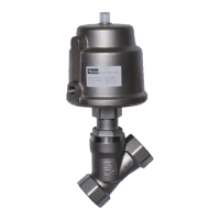
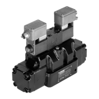
Design Proportional directional control valve,
direct operated (D*FC), pilot operated (D*1FC)
Actuation Proportional solenoid
Size D*FC
D*1FC
NG06 (CETOP 03) / NG10 (CETOP 05)
NG10 (CETOP 05) / NG16 (CETOP 07) / NG25 (CETOP 08) /
NG32 (CETOP10)
Mounting interface DIN 24340/ISO 4401/CETOP RP121/NFPA
Mounting position unrestricted
Hysteresis [%] <0.1
Ambient temperature [°C] -20...+60
MTTF
D
value
1)
[years] D*FC: 150, D*1FC: 75
Weight [kg] D*FC NG06 = 3.4 / NG10 = 7.7
D*1FC: NG10 = 9.0 / NG16 = 12.5 / NG25 = 21.0 / NG32 = 68.5
Vibration strength [G]
10 Sinus 5...2000 Hz acc. IEC 60068-2-6
10 (RMS) Random noise 20...2000 Hz acc. IEC 60068-2-36
15 Shock acc. IEC 60068-2-27
Hydraulic
Operating pressure [bar] D*FC: Ports P, A, B 350, port T max. 35; 210 (external drain);
port Y max. 35
D*1FC: pilot oil internal P, A, B, X 350; T, Y 210
pilot oil external P, A, B, T, X 350; Y 210
Fluid Hydraulic oil according to DIN 51524 ... 535, other on request
Fluid temperature [°C] -20...+60 (NBR: -25...+60)
Viscosity permitted
recommended
[cSt]/[mm2/s]
[cSt]/[mm2/s]
20…400
30...80
Filtration ISO 4406; 18/16/13
Electrical
Duty ratio [%] 100
Protection class IP65 acc. EN 60529 (with correctly mounted plug-in connector)
Supply voltage Us [VDC] 18...30, electric shut-off at < 17, ripple < 5 % eff., surge free
Current consumption max. [A] 2.0 (D1FC, D*1FC), 3.5 (D3FC)
Pre-fusing [A] 2.5 (D1FC, D*1FC), 4.0 (D3FC)
Command signal Uc
options
Ic
[V]
[mA]
[mA]
Codes B, K: +10...0...-10, ripple < 0.01 % eff., surge free,
Ri = 100 kOhm
Code S: 4...12...20, ripple < 0.01 % eff., surge free,
Ri = <250 Ohm
< 3.6 mA = enable off
> 3.8 mA = enable on (acc. NAMUR NE43)
Code E: +20...0...-20, ripple < 0.01 % eff., surge free, Ri = <250 Ohm
Differential input voltage
max.
[V]
[V]
[V]
[V]
Code 0/7: 30 for terminal D and E against PE (terminal G)
11 for terminal D and E against 0 V (terminal B)
Code 5: 30 for terminal 4 and 5 against PE (terminal W)
11 for terminal 4 and 5 against 0 V (terminal 2)
Adjustment ranges Min [%] 0...50
Max [%] 50...100
Ramp [s] 0...32.5
Interface RS232C, parametrizing connection 5pole
Enable signal (code 1/5/7) [V] 5...30
Diagnostic signal [V] +10...0...-10 / +12.5 error detection, rated max. 5 mA
EMC EN 61000-6-2, EN 61000-6-4
Central connection Code 0//7: 6+PE acc. EN 175201-804
Code 5: 11+PE acc. EN 175201-804
Cable specification [mm²]
[mm²]
Code 0/7: 7 x 1.0 (AWG16) overall braid shield
Code 5: 8 x 1.0 (AWG20) overall braid shield
Cable length max. [m] 50
1)
If valves with onboard electronics are used in safety-related parts of control systems, in case the safety function is requested, the
valve electronics voltage supply is to be switched off by a suitable switching element with sufficient reliability.
With electrical connections the protective conductor (PE W) must be connected according to the relevant regulations.

 Loading...