14
Prop. Directional Control Valve
Series D*FB / D*1FB
Operation Manual
Parker Hannifin CorporationParker Hannifin Corporation
D_FB-D_1FB_10-12 5715-669 UK.indd 25.06.19
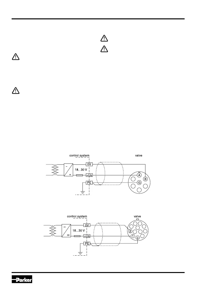
Wiring diagram of supply voltage
Code F0/M0/S0/G0 (6 + PE)
Code W5 (11 + PE)
Electrical interfacing
Supply voltage:
The supply voltage for the valve has to cover the
range of 18...30 V. The residual ripple may not ex-
ceed 5 % eff.
The applied power supply must comply to the
relevant regulations (DIN EN 61558) and must
carry a CE-mark. The operating voltage for
the valve must be free of inductive surges.
Do not exceed the max. value of 30 V Non-
observance of this rule may result in perma-
nent damaging of the valve.
The increased inrush current of the valve
should be considered when selecting the pow-
er supply. A stabilized power supply with over-
current limiting feature should not be used.
Due to the inrush current of the valve the cur-
rent limit circuit may respond prematurely and
create problems during energizing of the sup-
ply voltage.
The operation of the valve is blocked if the
supply voltage polarity is interchanged.
Each valve requires a separate pre-fuse (rat-
ing: s. techn. data). Non-observance of this
instruction may create irreparable damage of
valve resp. incorporated system parts.

 Loading...