4
Prop. Directional Control Valve
Series D*FB / D*1FB
Operation Manual
Parker Hannifin CorporationParker Hannifin Corporation
D_FB-D_1FB_10-12 5715-669 UK.indd 25.06.19
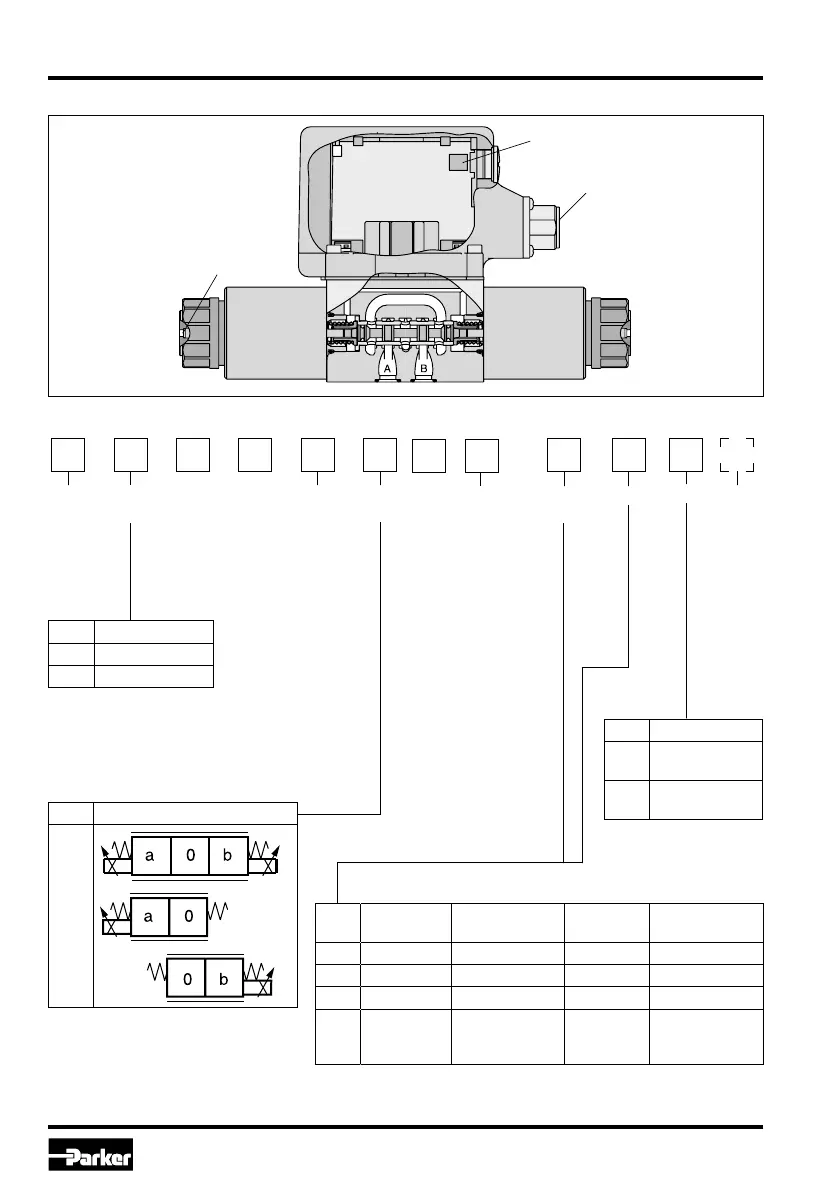
1. Introduction
Ordering code D*FB
Nominal
size
Direct.
control
valve
Spool-
type
(see
catalogue)
Command-
signal
Seal
NBR
(different seal
compound by
request)
Option
D
N
F
B
0
Code Nominal size
1 NG06 / CETOP 3
3 NG10 / CETOP 5
Code Spool position
C
E
K
Code
Command
signal
Function Connection
2)
Option
F0 0...+/-10 V 0...+10 V > P-A 6 + PE Pot.-supply
G0 0...+/-20 mA 0...+20 mA > P-A 6 + PE –
S0 4...20 mA 12...20 mA > P-A 6 + PE –
W5
1)
0...+/-10 V
4...20 mA
0...+10 V > P-A
12...20 mA > P-A
11 + PE
Pot.-supply &
command preset
channel
D*FB
Spool
position
Code Design
0
Spool/sleeve
design
3
Spool/body
design
Design
1)
Factory set +/-10 V
2)
Please order female connector separately.
Design
series
(not
required
for
ordering)
Parametrizing connection
Main connector
(always on B-side)
Manual
override