PBK 4 A1
GB
│
IE
│
NI
│
11 ■
Tightening and checking the saw chain
WARNING!
► Wear protective gloves! There is a danger of injury from the sharp
cutting teeth!
♦ Turn the chain-tensioner screw
in a clockwise direction using the
flat-blade screwdriver
to increase the tension.
♦ The saw chain
must lie against the underside of the blade. Check
whether the saw chain
can be drawn over the blade
by hand.
NOTE
►
A new saw chain stretches and must be tightened more frequently.
Lubricating the chain
♦ Remove the oil filler cap .
♦ Fill the oil tank
with approx. 100ml of organic chain oil
.
♦ The chain lubrication can be increased or decreased using the oil
adjusting screw
.
♦ Press and then turn the oil adjusting screw
clockwise to decrease
the chain lubrication.
♦ Press and then turn the oil adjusting screw
anticlockwise to increase
the chain lubrication.
WARNING!
► Never work without lubricating the chain first!
If the saw chain runs dry, the cutting equipment may become irrepar-
ably damaged within a short time. Always check chain lubrication
and oil level in the tank before starting work.
NOTE
► Use only saw chain oil. Preferably biodegradable. Do not use waste
oil, motor oil, etc.
► While working, check whether the chain lubrication is working
correctly.
Sharpening the saw chain
NOTE
► A bench grinder can be attached to the bench grinder support
for
a secure grip during grinding.
► You will find detailed information on sharpening in a sharpening set,
e.g. from Oregon.
► Alternatively, you can use an electrical saw chain sharpening device
and follow the manufacturer's instructions.
► If you have any doubts about carrying out the work, the saw chain
should be replaced.
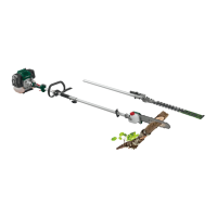
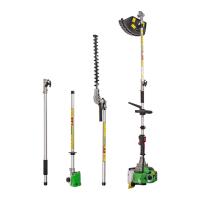
Attaching the extension attachment
CAUTION!
■ Do not use the extension attachment/boom
in combination with
the 3-section cutting blade/strimmer attachment!
NOTE
► Use the extension attachment/boom
for working at greater
heights.
♦ Fit the extension attachment/boom
between the engine unit and
the hedge trimmer/pole pruner. The assembly is carried out in the
same manner as for the attachments described previously.
Fitting/removing the protective guard
WARNING!
■ When working with the 3-section cutting blade
, the blade guard
must be fitted. The blade guard is positioned under the metal panel
of the boom . The blade guard is now attached to the front boom
with the 2 screws . To do this, use the supplied hex key
.
Cutting equipment Protective equipment
3-section cutting blade Blade guard
Strimmer
Blade guard + cutting filament
protective guard
C
WARNING!
► Do not use any other cutting equipment apart from that which is
supplied with the product. The use of any other cutting equipment
or protective equipment is deemed to be improper and carries a
significant risk of accidents.
Installing/replacing the cutting blade
■ Fit/remove the 3-section cutting blade as shown in figures 1a–1f.
ATTENTION! Left-hand thread!
■ Find the hole in the drive plate
, align it with the opposite hole and
block it with the supplied hex key
.
■ Place the 3-section cutting blade on the drive plate
(see fig. 1b).
The inscription must be visible from above when holding the tool in the
working position (see fold-out page). Both sides of the 3-section cutting
blade
can be used.
■ Fit the pressure plate
over the thread over the splined shaft
(see fig. 1c).
■ Fit the pressure plate cover
(see fig. 1d).
■ Tighten the nut
with the spark plug spanner
anticlockwise
CAUTION! Left-hand thread! (see fig. 1f).
■ The 3-section cutting blade
is fitted with a plastic cover on delivery.
This must be removed before use and refitted during periods when not
in use.
■ The plastic cover can now be removed.
CAUTION! SHARP EDGES, WEAR PROTECTIVE GLOVES!
■ Fit the cutting filament protective guard
C
on the protective guard .
■ The cutting filament protective guard
C
must be fitted when working
with the cutting filament. The cutting filament protective guard
C
(pre-fitted on delivery) is fitted as shown in figure 2a.
■ Ensure that the cutting filament protective guard
C
is correctly clicked
into place. There is a blade
A
on the inside of the cutting filament
protective guard
C
. This is covered with a safety cover (see fig. 2a.).
■ Remove the safety cover before starting work and replace it after finish-
ing work.
CAUTION! SHARP EDGES, WEAR PROTECTIVE GLOVES!
■ To remove the cutting filament protective guard
C
from the protective
guard , take a tool, such as a screwdriver, to carefully remove the
three mounting pins.
ATTENTION! RISK OF INJURY!
 Loading...