h
oN [*.]-'liLVJlk_l:i'4[a):]LvJq_l
Provide the following minimum clearances to
combustible construction• See Figure i.
.,i [I,{.]_VJl:{l_"_l/[e]_._lf±lL'_llp]ivJ::lL_b/llV___l/[O]l._lV'_II;
2,
3.
4,
I Sides: 6"
2. Rear of Jacket: 6"
3. Front of Jacket: 24**
4. Top of Jacket: 24"
5. Steam and Hot Water Pipes: 6"
6. Vent or Chimney Connector: 18"
The installation must provide adequate air for
combustion and ventilation.
Unless the boiler room construction and natural air
infiltration are sure to provide all the air needed,
provide an opening or duct to the outside with a free
cross sectional area of at least I square inch per
4000 Btuh input for all installed appliances. At high
altitude, increase this requirement 4% for each i000
feet above sea level.
The boiler room must never be under negative
pressure. If exhaust fans or other equipment can
cause a negative pressure in the boiler room, the air
openings and equipment design must be engineered
to assure a neutral or slightly positive pressure in the
boiler room at all times of operation. If the
equipment design and air openings cannot assure
this, then the boiler must be located in an isolated
rOOM.
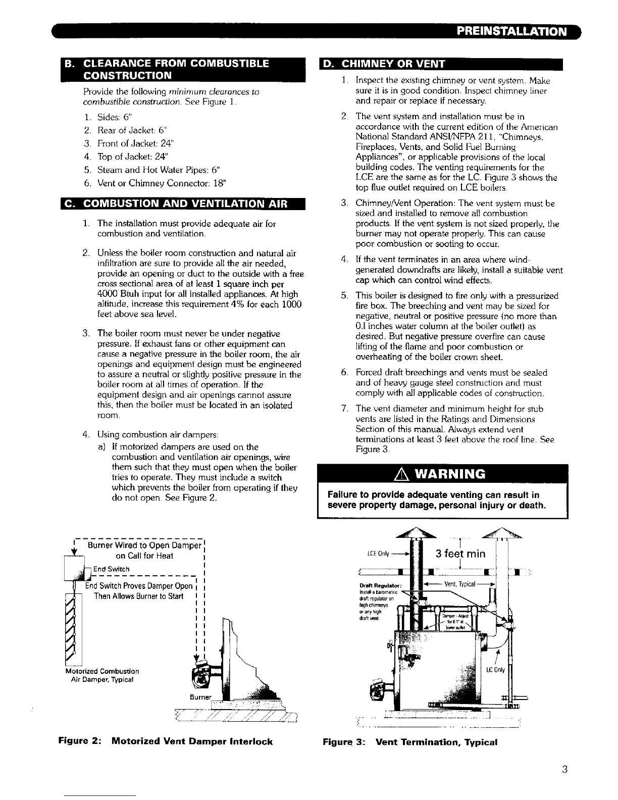
Using combustion air dampers:
a) If motorized dampers are used on the
combustion and ventilation air openings, wire
them such that they must open when the boiler
tries to operate• They must include a switch
which prevents the boiler from operating if they
do not open. See Figure 2.
I.
2
3.
4.
5.
6.
7.
Inspect the existing chimney or vent system Make
sure it is in good condition• Inspect chimney liner
and repair or replace if necessary•
The vent system and installation must be in
accordance with the current edition of the American
National Standard ANSI/NFPA 21 i, "Chimneys,
Fireplaces, Vents, and Solid Fuel Burning
Appliances", or applicable provisions of the local
building codes. The venting requirements for the
LCE are the same as for the LC. Figure 3 shows the
top flue outlet required on LCE boilers
Chimney/Vent Operation: The vent system must be
sized and installed to remove all combustion
products. If the vent system is not sized properly, the
burner may not operate properly. This can cause
poor combustion or sooting to occur.
If the vent terminates in an area where wind-
generated downdrafts are likely, install a suitable vent
cap which can control wind effects.
This boiler is designed to fire only with a pressurized
fire box. The breeching and vent may be sized for
negative, neutral or positive pressure (no more than
0.I inches water column at the boiler outlet) as
desired. But negative pressure overfire can cause
lifting of the flame and poor combustion or
overheating of the boiler crown sheet•
Forced draft breechings and vents must be sealed
and of heavy gauge steel construction and must
comply with all applicable codes of construction.
The vent diameter and minimum height for stub
vents are listed in the Ratings and Dimensions
Section of this manual. Always extend vent
terminations at least 3 feet above the roof line. See
Figure 3.
Failure to provide adequate venting can result in
severe property damage, personal injury or death.
I Burner Wired to Open Damper
i_ on Call for Heat
EdSdw/_cV-htC-phrovesDamper Open
Then Allows Burner to Start
Motorized Combustion
Air Damper, Typical
Burner
Figure 2: Motorized Vent Dumper Interlock
Figure 3: Vent Termination, Typical
 Loading...