III:(_i i/.l-, :_']f!_"
JR ILl'_[_ Ir'.._UHNIl{_o]lNl_,,_[o];| I_IIF,.._IUI:::F_
=I lii'i.];{o]_lL'l|[@/1511/II1:1.]1111
1+
2.
3.
4.
5.
6,
Remove the coil cover plates, gaskets and mounting
hardware, located in the Flue Box Carton•
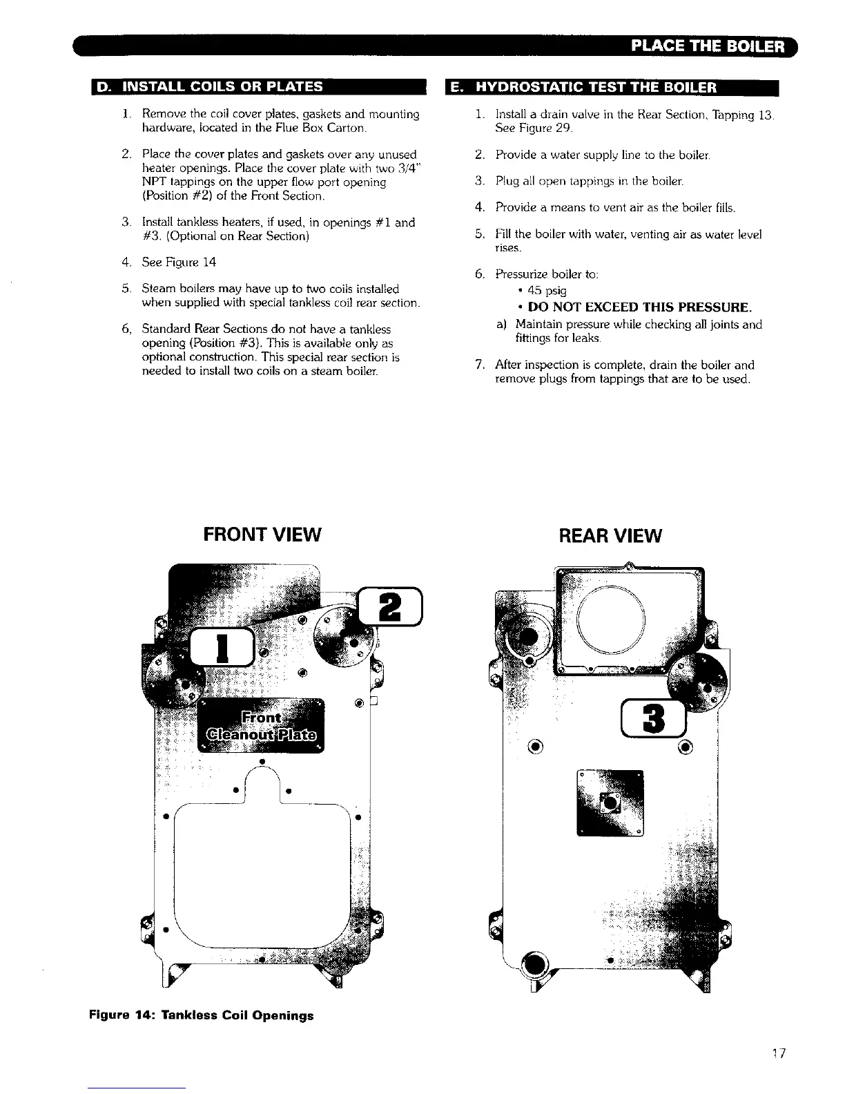
Place the cover plates and gaskets over any unused
heater openings• Place the cover plate with two 3/4"
NPT tappings on the upper flow port opening
(Position #2) of the Front Section•
Install tankless heaters, if used, in openings #i and
#3, (Optional on Rear Section)
See Figure 14
Steam boilers may have up to two coils installed
when supplied with special tankless coil rear section•
Standard Rear Sections do not have a tankless
opening (Position #3). This is available only as
optional constroction. This special rear section is
needed to install two coils on a steam boiler
1. Install a drain valve in the Rear Section, Tapping 13
See Figure 29.
2. Provide a water supply line to the boiler
3. Plug all open tappings in the boiler
4. Provide a means to vent air as the boiler fills.
5. Fill the boiler with water, venting air as water level
rises.
6. Pressurize boiler to:
• 45 psig
• DO NOT EXCEED THIS PRESSURE.
a) Maintain pressure while checking all joints and
fittings for leaks•
7. After inspection is complete, drain the boiler and
remove plugs from tappings that are to be used.
FRONT VIEW
REAR VIEW
Figure 14: Tankless Coil Openings
17
 Loading...