Mechanical Instructions
EN 19QFU1.2E LA 4.
2014-Jan-10
back to
div. table
Figure 4-17 Rear cover removal Ambilight models -2-
4.3.2 Ambilight units in Rear Cover
The Ambilight units are affixed in the rear cover and will self-
destruct upon removal.
Attention: it is of the utmost importance to remove all remains
of any adhesive that might be left on the inside of the rear
cover.
The new units come with double-sided adhesive tape. Ensure
a correct mounting to avoid uneven light emission of the units.
4.3.3 SSB
Refer to Figure 4-18
and Figure 4-19 for details.
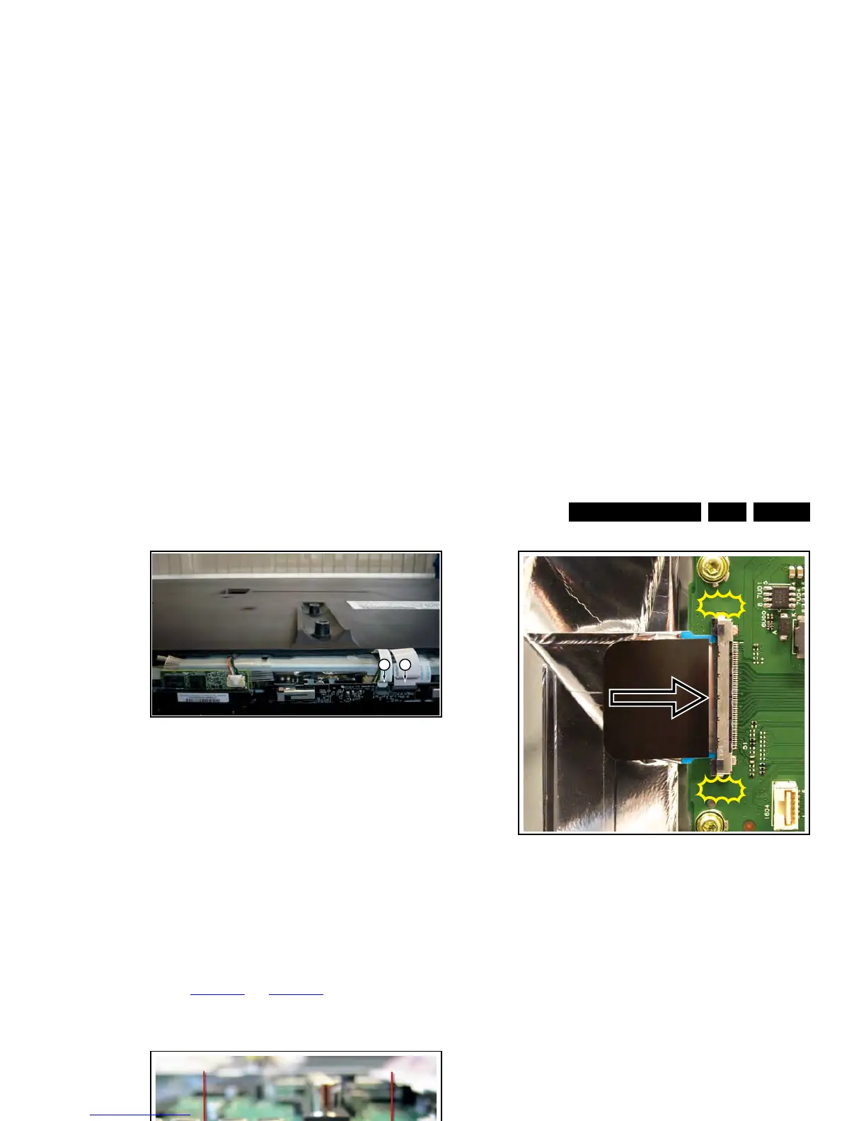
Some SSBs have a dedicated LVDS connector, requiring
pressing two catches as indicated in the figure, before
removing the LVDS cable.
Figure 4-18 SSB LVDS connector catches (optional) -1-
Upon re-connecting the LVDS cable, ensure the catches are
locked after having inserted the LVDS cable.
Figure 4-19 SSB LVDS connector catches (optional) -2-
4.4 Set Re-assembly
To re-assemble the whole set, execute all processes in reverse
order.
Notes:
• While re-assembling, make sure that all cables are placed
and connected in their original position.
• Pay special attention not to damage the EMC foams in the
set. Ensure that EMC foams are mounted correctly.
 Loading...