Wiring
Operating Manual PDP67 F 4 code
1001531-EN-06
13
6 Wiring
6.1 General wiring guidelines
Please note:
} Information given in the “Technical details” must be followed.
} Where safety-related applications are concerned, it is essential that short circuits and
open circuits are unable to cause a hazardous condition within a plant. The way in
which this is done will depend on the degree of hazard from the plant, the switching fre-
quency of the sensors and the level of safety of the sensors and actuators.
} You can use prefabricated sensor cables from Pilz for connecting the sensors.
CAUTION!
In order to guarantee protection type IP67, unused plug-in connectors
should be sealed using the blind plugs supplied.
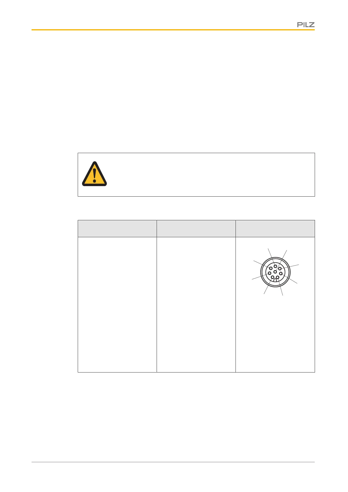
6.2 Assignment of female connectors
Inputs/outputs
X1 to X4
Assignment
8-pin M12 female connect-
ors for connecting the
sensors
1: input I2 (S21)
2: 24 VDC (A1)
3: Output O1 (12)
4: Output O2 (22)
5: Signal output Diag (Y32)
6. Input I1 (S11)
7. 0 V (A2)
8. Input lock for control com-
mand for magnetic guard
locking (S31)

 Loading...


