3Operating Manual
ENGLISH
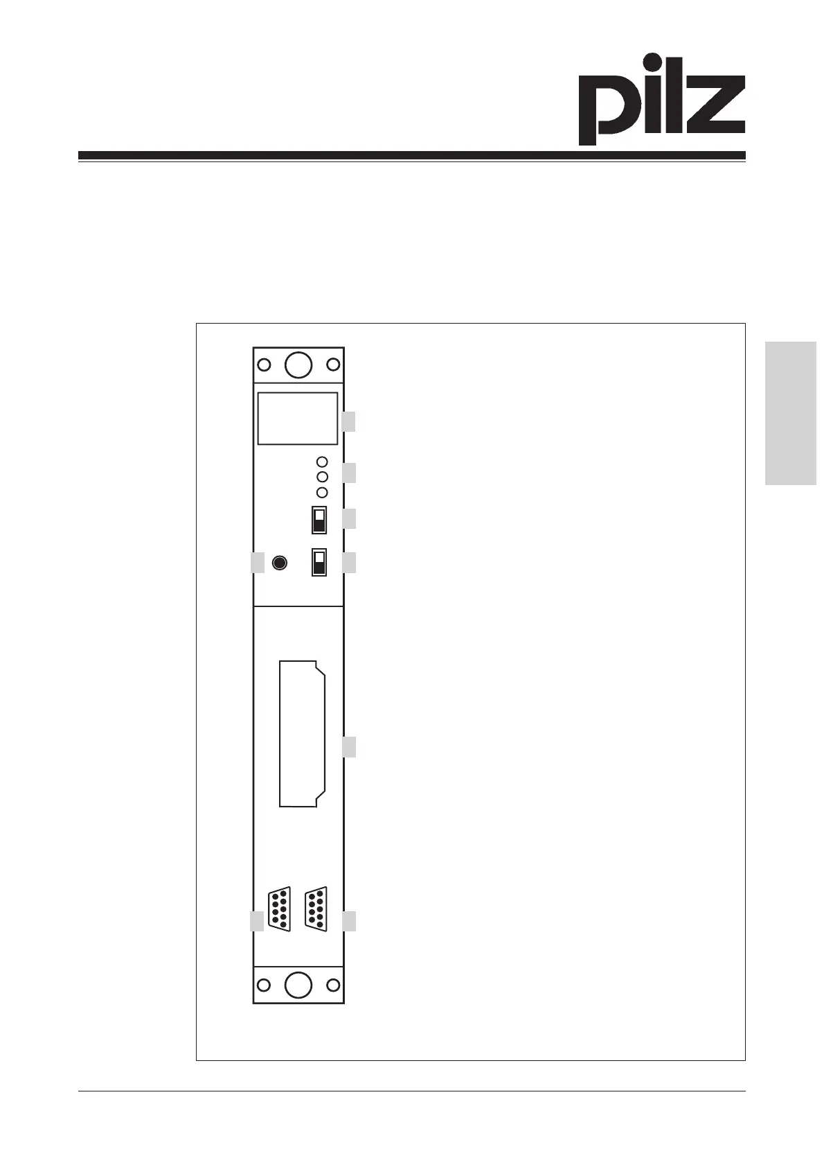
Fig. 1: Front view of the PSS CPU, PSS1 CPU, PSS SF CPU and PSS1 SF CPU
RUN
PG
RUN
POWER
RUN
STOP
ST
FS
AUTO PG
SPS
ST
FS
F-STACK
3
1
2
4 5
6
7 8
1: Four-digit display
2: LEDs for operating mode and mains
voltage
3: Three-position switch for selecting the
standard section's operating mode
4: Button for scrolling the error stack
5: Two-position switch for selecting the
failsafe section's operating mode
6: Slot for the standard section's
program memory cartridge
7: RS 485 programming interface
8: RS 232 user interface
• PSS CPU, PSS1 CPU, PSS SF CPU, PSS1 SF CPU: Slot for the
standard section's program memory cartridge.
The CPU is installed on a designated slot on the module rack. Various
power supplies are available.
 Loading...


