4 Operating Manual
Series PSS CPU/PSS1 CPU
RUN
PG
RUN
POWER
RUN
STOP
ST
FS
AUTO PG
SPS
ST
FS
F-STACK
3
PGRS 2312/485
1
2
4 5
6
7
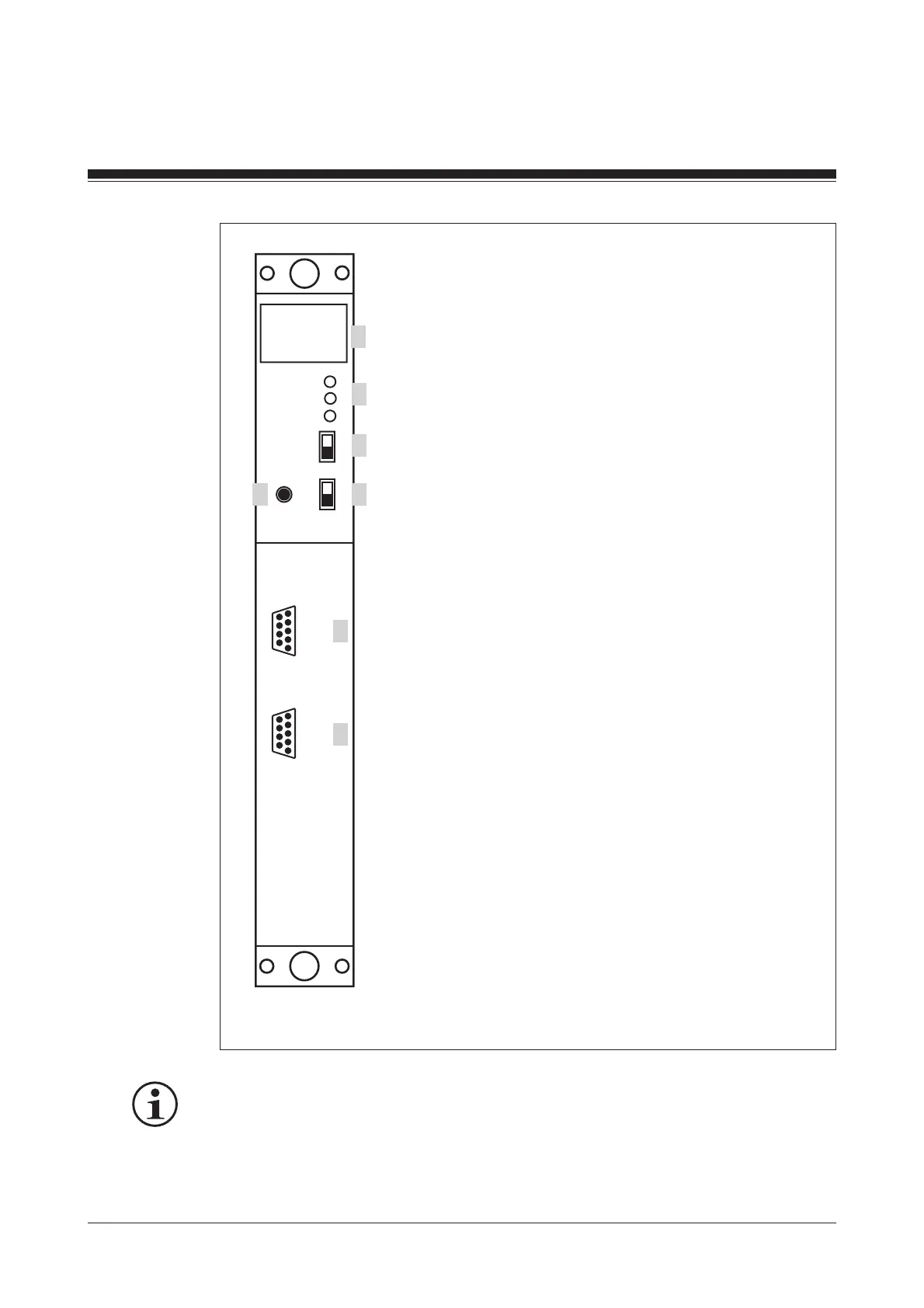
1: Four-digit display
2: LEDs for operating mode and mains
voltage
3: Three-position switch for selecting the
standard section's operating mode
4: Button for scrolling the error stack
5: Two-position switch for selecting the
failsafe section's operating mode
6: RS 232 / RS 485 programming
interface
7: RS 232 / RS 485 user interface
Fig. 2: Front view of the PSS CPU 2 and PSS1 CPU 2
INFO
A detailed description of the interface can be found in the “PSS 3000/PSS
3100 Series Installation Manual”.
For further information please refer to the PSS "System Manual”.