5/12
Monitoring of movable guards and magnetic safety
sensors
The safety module can monitor emergency stop circuits,
control circuits for movable guards as well as magnetic
safety sensors. Replace the emergency stop contacts with
switch contacts or sensor contacts.
Magnetic sensors can be connected only in dual
channel configuration.
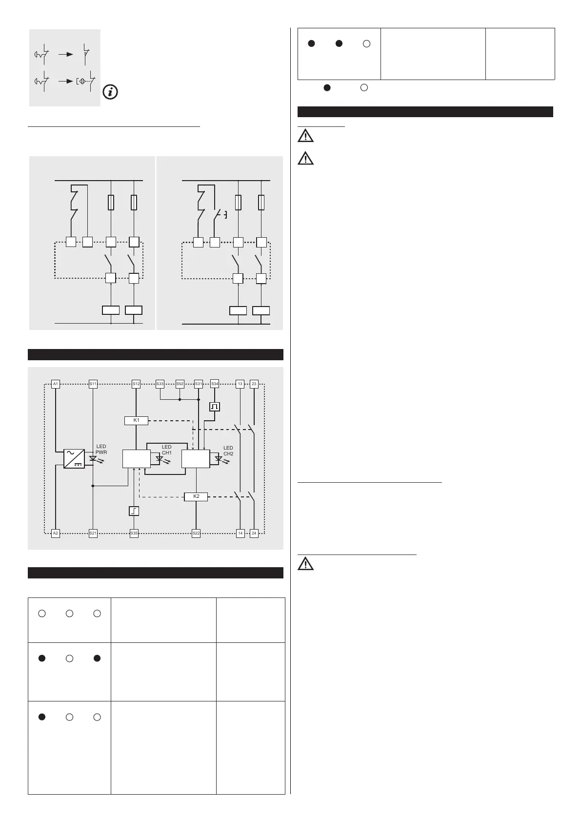
4.3 Increase of number and load capacity of contacts
If necessary the number and the load capacity of output contacts can be increased by
using external contactors with forcibly guided contacts.
Feedback circuit for external contactors
with automatic start
Feedback circuit for external contactors
with manual or monitored start
K3
K3
K4
K4
F
F
N /-
L /+
S33
S34 13 23
14
24
K3
K3
K4
K4
F
F
N /-
L /+
S33
S34 13 23
14
24
5 INTERNAL WIRING DIAGRAM
L / +
N / -
LOGIC LOGIC
6 FAULTS
LED state Possible fault Recommended action
PWR
CH1 CH2
- No power supply to the module.
- Wrong wiring.
- Power supply conductor/s cut.
- External fuse broken.
- Short circuit between channels.
- Internal module fault.
Check the wiring and
check the fuse.
If the fault persists,
replace the module.
PWR
CH1 CH2
- Wrong wiring.
- Sticking of the contact of the
emergency stop button or of the
control device for movable guards
connected to S21-S22.
- Sticking of the start button
contact (monitored start).
- Internal module fault.
Check the wiring, the
start switch and the
emergency stop
button/control device
for guards.
If the fault persists,
replace the module.
PWR
CH1 CH2
- Wrong wiring.
- External contactors welded or
expansion module failure.
- Contactor/s cut.
- One or both contacts of the
emergency stop button or of
the control devices for movable
guards are open.
- Activation cycle for manual or
monitored start (start impulse)
missing or both channels for the
automatic start closed.
- Internal module fault.
Check the wiring, the
input channels and
the start configura-
tion.
If the fault persists,
replace the module.
PWR CH1 CH2
- Sticking of the contact of the
emergency stop button or of the
control device for movable guards
connected to S11-S12.
- Internal module fault.
Check the wiring, the
start switch and the
emergency stop
button/control device
for guards.
If the fault persists,
replace the module.
Legend:
= led on; = led off.
7 INSTRUCTIONS FOR PROPER USE
7.1 Installation
Attention: Do not exceed the tightening torques specified for the terminal screws
in the present manual.
Attention: Observe the wiring of the terminals: incorrect wiring can damage the
device which may result in loss of the safety function.
- Install only inside a cabinet with protection degree not less than IP54 according to
EN 60529.
- Always affix the device with the specific DIN rail adaptor acc. to EN 60715.
- Do not stress the device with bending and torsion.
- Do not modify or open the device for any reason.
- The device carries out an operator protection function. Any inadequate installation
or tampering can cause serious injuries and even death, property damage, and eco-
nomic losses.
- These devices must not be bypassed, removed or disabled in any other way.
- If the machine where the device is installed is used for a purpose other than that
specified, the device may not provide the operator with efficient protection.
- The safety category of the system (according to EN ISO 13849-1), including the
safety device, also depends on the external components connected to it and their
type.
- Before installation, make sure the device is not damaged in any part.
- Before commissioning, check the correct functioning of the module according to the
instructions of the operating diagrams (see paragraph OPERATION).
- Avoid excessive bending of connection cables in order to prevent any short circuits
or power failures.
- Do not paint or varnish the device.
- Do not drill the device.
- Do not use the device as a support or rest for other structures, such as raceways,
sliding guides or similar.
- Before commissioning, make sure that the entire machine (or system) complies with
all applicable standards and EMC directive requirements.
- The documents necessary for a correct installation and maintenance are always
available in the following languages: English, French, German and Italian.
- Should the installer be unable to fully understand the documents, the product must
not be installed and the necessary assistance may be requested from the manufac-
turer (see paragraph SUPPORT).
- Always attach the following instructions to the manual of the machine in which the
device is installed.
- These operating instructions must be kept available for consultation at any time and
for the whole period of use of the device.
7.2 Do not use in the following environments
- In environments where continual changes in temperature cause the formation of
condensation inside the device.
- In environments where the application causes the device to be subjected to strong
impacts or vibrations.
- In environments with the presence of explosive or flammable gases or dusts.
- In environments containing strongly aggressive chemicals, where the products used
coming into contact with the device may impair its physical or functional integrity.
7.3 Maintenance and functional tests
Attention: Do not disassemble or try to repair the device. In case of any malfunc-
tion or failure, replace the entire device.
- The device installer is responsible for establishing the sequence of functional tests
to which the device is to be subjected before the machine is started up and during
maintenance intervals.
- The sequence of the functional tests can vary depending on the machine complex-
ity and circuit diagram, therefore the functional test sequence detailed below is to be
considered as minimal and not exhaustive.
- Perform the following sequence of checks before the machine is commissioned and
at least once a year (or after a prolonged shutdown):
1) Check that the safety module housing is undamaged and in good condition. If the
housing is damaged, replace the entire device.
2) Check that all signalling LEDs are working.
3) Check that the electrical cables are firmly lodged inside the terminals and con-
nectors.
4) While the machine is moving, open a guard and/or press an emergency stop but-
ton (these devices must be electrically connected to the safety module). The machine
must stop immediately. The stopping time of the machine must be always shorter than
the time required by the operator for opening the guard and reaching the dangerous
parts.
5) Try to start the machine while the guard is open and/or an emergency stop button
is pressed. The machine must not start.
- The device has been created for applications in dangerous environments, therefore
it has a limited service life. Although still functioning, after 20 years from the date
of manufacture the device must be replaced completely. The date of manufacture is
placed next to the product code (see paragraph MARKINGS).
 Loading...