10.3
ELECTRICAL
10
P
RELIMINARY
V
ERS
I
ON
GENERAL INFORMATION
Special Tools
Electrical Service Notes
Keep the following notes in mind when diagnosing an electrical
problem:
• Refer to wiring diagram for stator and electrical
component resistance specifications.
• When measuring resistance of a component that has a
resistance value under 10 Ohms, remember to subtract
meter lead resistance from the reading. Connect the
leads together and record the resistance. The resistance
of the component is equal to tested value minus the lead
resistance.
• Become familiar with the operation of your meter. Be
sure leads are in the proper jack for the test being
performed (i.e. 10A jack for current readings). Refer to
the Owner’s Manual included with your meter for more
information.
• Voltage, amperage, and resistance values included in
this manual are obtained with a Fluke™ 77 Digital
Multimeter (PV-43568). This meter is used when
diagnosing electrical problems. Readings obtained with
other meters may differ.
• Pay attention to the prefix on the multimeter reading (K,
M, etc.) and the position of the decimal point.
• For resistance readings, isolate the component to be
tested. Disconnect it from the wiring harness or power
supply.
Under-Dash Components
The following switches and components can be accessed
underneath the instrument / dash panel:
• Speedometer
• Speedometer Mode Switch
• Digital Wrench Diagnostic Connector
• Digital Wrench / ECU Reflash 9 Vdc Battery Plug
• AWD Switch
• Headlamp Switch
• 12 Vdc Accessory Power Point
• Ignition Switch
• Fuse / Relay Panel
SWITCHES / CONTROLS
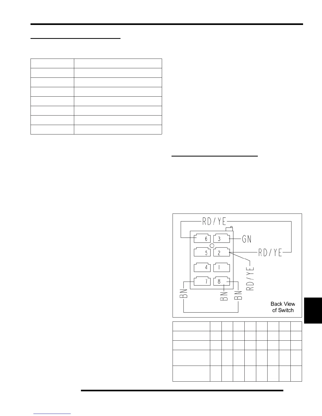
Headlamp Switch
1. Disconnect the headlamp switch harness (Brown, Green,
and Red/Yellow), by depressing the connector lock and
pulling on the connector. Do not pull on the wiring.
2. Test the switch connections and check for continuity at the
following pins as shown in the illustration.
Part Number Tool Description
PV-43568 Fluke™ 77 Digital Multimeter
PV-43526 Connector Test Kit
2870630 Timing Light
2870836 Battery Hydrometer
2460761 Hall Effect Sensor Probe Harness
2871745 Static Timing Light Harness
- Digital Wrench™ (see Chapter 4)
12345678
ON X X
OFF
SWITCH
BACK-LIGHT
XX
ON
INDICATOR
XX

 Loading...


