Installing The SoundStructure C16, C12, C8, And SR12
2 - 19
Chapter 4 Logic Examples provides an example of how to use the analog gain
input pin.
Logic Outputs
All logic outputs are configured as open-collector circuits and may be used
with external voltage sources. The maximum voltage that should be used with
the logic outputs is 60 V with a maximum current of 500 mA.
The open collector design is shown in the following figure and works as a
switch as follows: when the logic output pin is set high (on), the transistor will
turn on and the signal connected to the logic output pin will be grounded and
current will flow from the logic output pin to chassis ground.
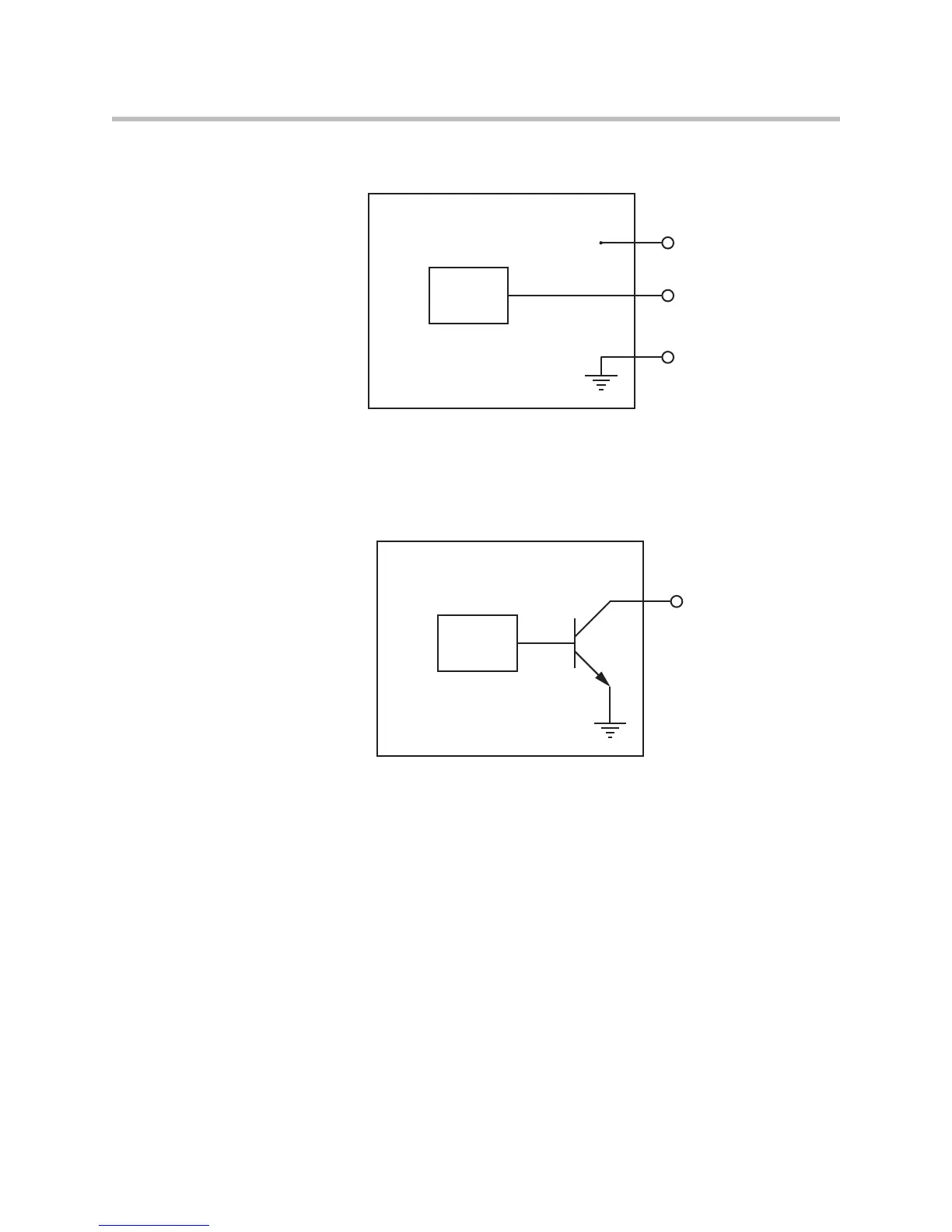
Analog
Voltage
Value
SoundStructure Logic Input
Analog Gain Input Pin
Logic Pin 25 (Ground)
Logic Pin 1 (+5V)
5V
Logic
Controller
SoundStructure Logic Output
Logic Output Pin
Chassis
Ground
 Loading...