3
3
Should you encounter any problems, contact the Customer Service Representative/Parts Department at (800) 813-0206
from 8 AM to 5 PM Mon. thru Fri. EST. Extended operating days and hours during peak season requirements.
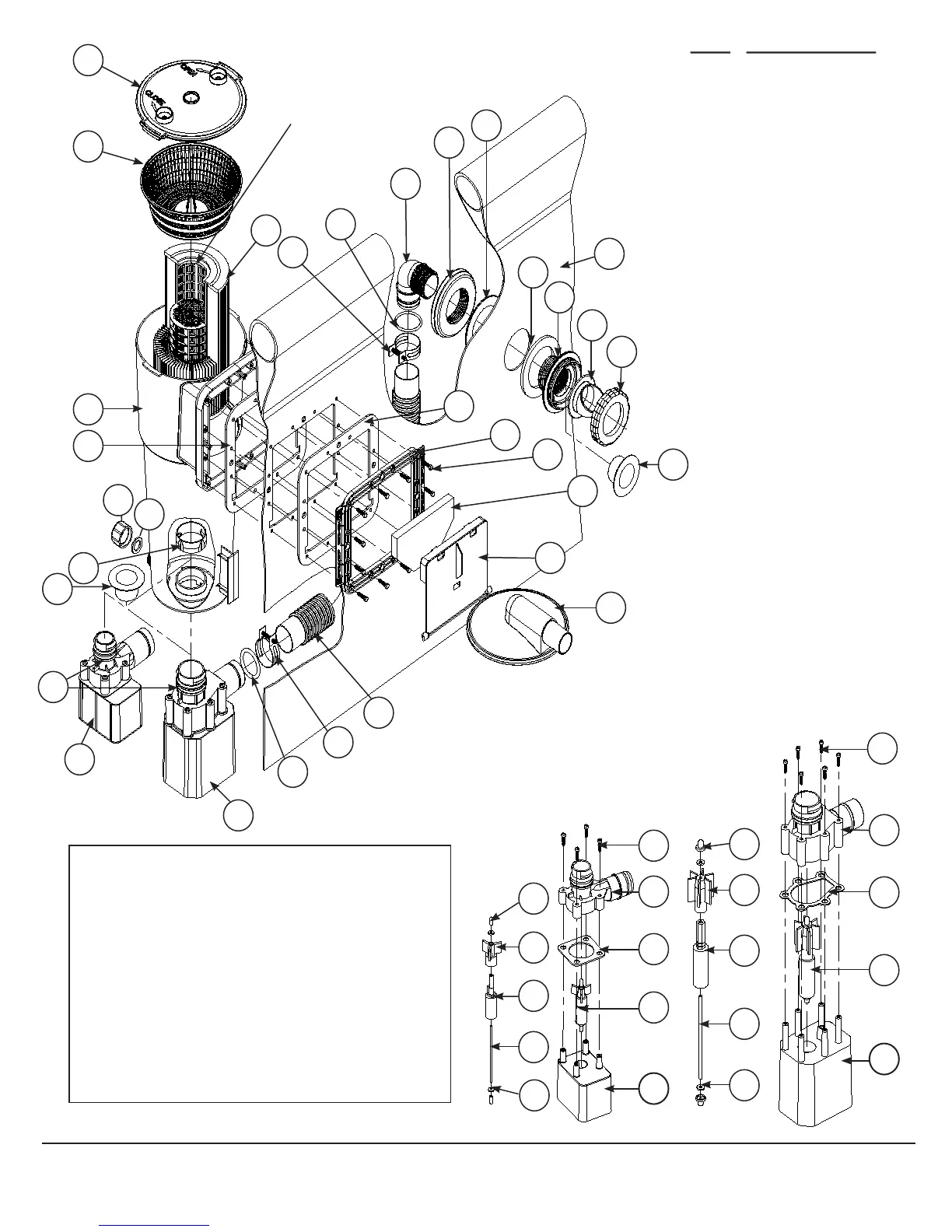
FIG. 1
THE FILTER CARTRIDGE (9) WILL HOLD 1”
DIAMETER CHLORINE TABLETS. CHECK
YOUR CHLORINE LEVELS TO DETERMINE
THE PROPER NUMBER OF TABLETS
TO ADD.
YOU MUST
HAVE THIS
TYPE OF
FILTER WITH
A CENTRAL
CORE MESH
DIVIDER
TO USE THE
CHLORINE
DISPENSER.
US PATENT
# 7,005,062
11
10
9
8
22
7
1 - 6
12
14
13
26
25
23
22
24
16
15
20
21
32
17
18
19
12
14
5
3
4
2
2B
2A
2C
2D
2E
12 EA.
6 EA.
2 EA.
2 EA.
1
27
1 - 6
2B
2C
2A
2D
2E
2 EA.
2 EA.
5
3
4
2
4 EA.
1
F600C & F700C F1000C / F1500C / F2000C
PATENT
PENDING
FILTER
SYSTEM
6
28
29
IMPORTANT! Your pump is protected by a thermal
overload. This device senses the temperature of the pump
and if it is getting too hot, it will open the electric circuit
and the pump will stop running until it cools off some. It
will automatically turn back on when it has cooled down
enough. This is a safety device to help prevent excessive
pump damage.
If your pump is doing this, it is because of high pool water
temperature and/or high air temperature and/or low water
flow thru the pump. If this happens you need to check
water flow thru the filter and correct it if needed. This
pump uses the water flow for cooling. You may also want
to run the pump at night when the temperature is lower.
When Pump (1) needs servicing or working on Return
Hose (13), turn off power and install the Service Plug
(30) into Pool Wall Fitting (15) after removing Locking
Ring (21) and Diverter Fitting (20). Also install a Service
Plug (30) into center hole of the Skimmer Canister (8)
after removing the Pump Retaining Nut (7). See FIG. 1.
When service is complete remove both Service Plugs (30)
reversing the procedures above.
NOTE:
30
30
NOTE:
Install Service
Plugs (30)
only when
servicing
system!
KEY DESCRIPTION
1 PUMP BODY W/CORD
2 ROTOR ASSEMBLY
2A MAGNET AXLE
2B IMPELLER
2C SHAFT
2D THRUST WASHERS
2E SHAFT END CAPS
3 PUMP GASKET
4 VOLUTE HOUSING
5 PHILLIPS HEAD SCREWS
6 O-RING
7 PUMP RETAINING NUT
8 SKIMMER CANISTER
9 FILTER CARTRIDGE
10 STRAINER BASKET
11 LOCK TOP
12 O-RING
13 RETURN HOSE
14 HOSE CLAMP
15 POOL WALL FITTING
16 GASKET
17 THRUST WASHER
18 NUT
19 ELBOW 90°
20 DIVERTER FITTING
21 LOCKING RING
22 GASKET
23 FACE PLATE
24 HEX HEAD SCREWS
25 WEIR FOAM
26 WEIR
27 VACUUM ADAPTER
28 DRAIN CAP
29 SEAL GASKET
30 SERVICE PLUGS
32 POOL WALL
 Loading...