4
4
1. POWER FILTER INSTALLATION: (REFERENCE PAGE 3, FIG. 1)
WARNING - EXTREMELY IMPORTANT!
• Risk of electrical shock, connect only to a grounding type receptacle protected by a
ground fault circuit interrupter, (GFCI). Contact a qualified electrician if you cannot
verify that the receptacle is protected by a GFCI.
• Receptacle must be at least 10 feet away from pool.
• Filter system can be used as many hours as desired, but NEVER when the pool is
occupied.
• Do not use an extension cord to connect unit to electric supply; provide a properly
located outlet.
• Do not bury the cord.
NOTE - The Power Filter will be in four sections: a pump; filter assembly; hardware
bag; and return hose.
A. First, Locate the filter assembly, remove the Lock Top (11), Strainer Basket (10),
and Filter Cartridge (9) from the assembled Filter Case. Locate the mounting location for the power filter on the Pool Wall
(32). Install one Gasket (22) over the four alignment pins on the skimmer canister (8) and place it up to the outside pool
wall inserting the four alignment pins through the four large holes in pool wall. Now leaning against the Skimmer to hold it
in place add the inside gasket (22) over the pins on the inside of the pool wall. Now place the Face Plate (23) over the align-
ment pins. Place the Hex Head Screws (24) into their holes. Start all the Hex Head Screws one and a half turns each. Then
proceed in tightening them in equal turns each in sequence around the Face Plate until all are equally tight and you have a
good even seal. Warning! Be sure not to over tighten them, you just need a water tight seal.
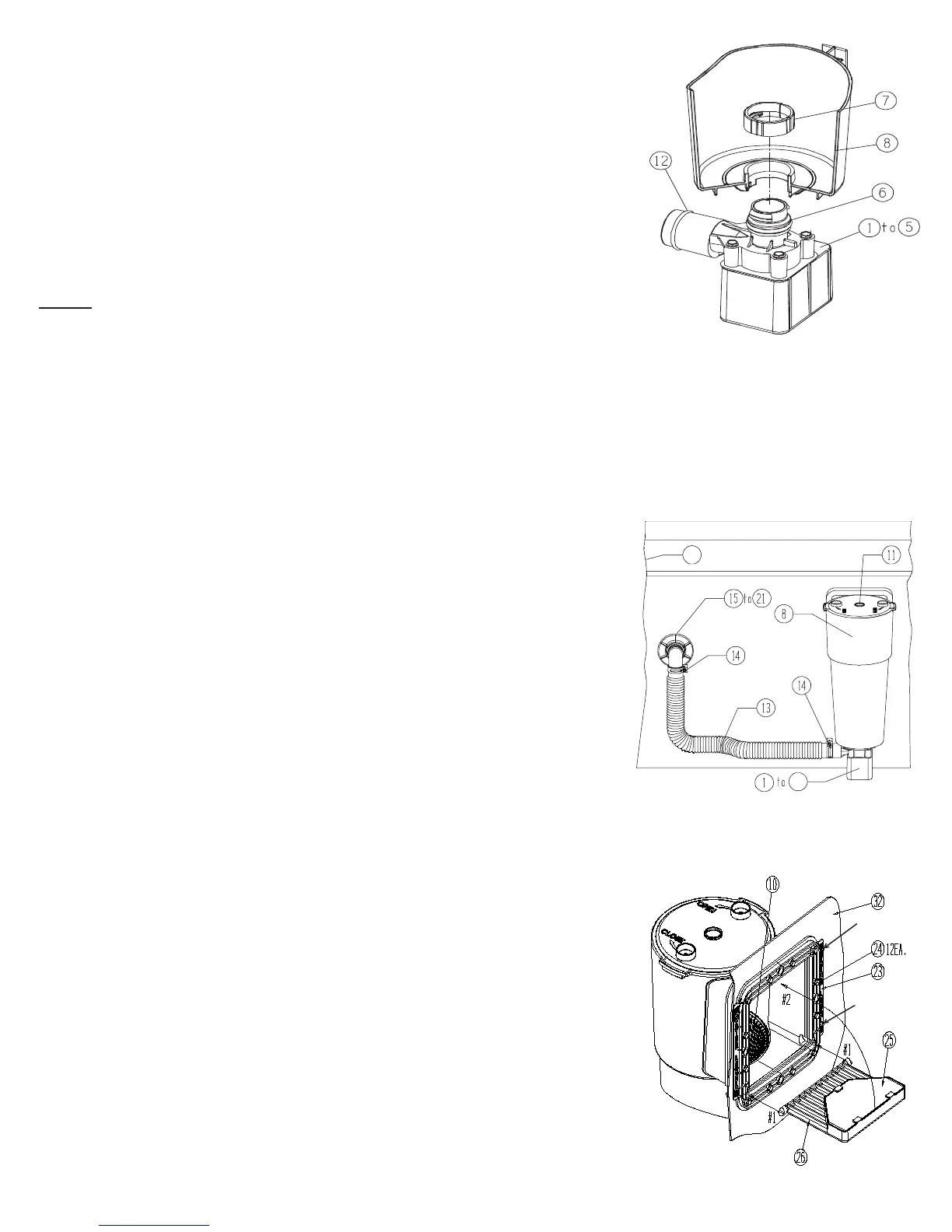
B. Now lubricate the pump O-ring (6) with petroleum jelly (not provided). Hold the Skimmer Canister (8) securely, and insert
pump assembly (1-6) so that the outlet on the Volute Housing (4) extends out to
the side of the canister as shown in Fig. 2. Insert the pump until it bottoms out,
and the two ribs on the volute housing insert into the two slots on the bottom of
the canister. Reach down inside the canister and place the Pump Retaining Nut
(7) over the top of the volute housing inlet as shown in Fig. 2. Twist the Nut (7)
clockwise until it is snug.
C. Locate the Pool Wall Fitting assembly parts (15-21). Lubricate the black Wall
Fitting Gasket (16) with petroleum jelly and install it over the threads on the Pool
Wall Fitting (15). Insert the pool wall fitting with the gasket through the hole in
the wall from the inside of the pool. Place the Thrust Washer (17) over the pool
wall fitting and then thread the Wall Fitting Nut (18) onto the fitting until it is hand
tight. DO NOT over tighten the wall fitting nut or wrinkle the pool wall around
the Wall Fitting Thrust Washer (17) or Wall Fitting Gasket (16). Now apply some
petroleum jelly to the thread of the Elbow 90° (19) and install the elbow into the
wall fitting assembly. Install the Diverter Fitting (20) and Locking Ring (21) onto the wall fitting.
D. Get the Return Hose (13) and remove the two Hose Clamps (14) from the hardware bag. Loosen the hose clamps and slide
them over the end of the hose. It is recommended to lubricate the O-Rings (12) on the Volute Housing (4) and on the Elbow
(19) before installing the hose (13). Install the hose on the pump volute housing
and on the Elbow (19). Tighten both of the Hose Clamps (14). See Fig. 3.
E. Place the Filter Cartridge (9) and the Strainer Basket (10) back into the Skim-
mer Canister (8). It is important that the Filter Cartridge (9) slips over the Pump
Retaining Nut (7) and seals at the bottom of the canister so that the Strainer
Basket (10) will seat in it’s groove inside the canister. See Fig. 4. Place the Lock
Top (11) on top of the Skimmer Canister (8) and lock it in place by turning it
clockwise until it is locked. Push the Weir Foam Pad (25) into the Weir (26) and
under the tabs, to hold it in place. Take the Weir (26) and slide it into the grooves
from inside the pool. See Fig. 4. Once the weir is pushed inside the grooves, flip it
over as shown by the Arrow #2 in Fig. 4, to lock it in place. NOTE: The weir can
ONLY be pushed into the grooves as shown by Arrows #1 in Fig. 4, by holding
it horizontal. Be sure the weir moves freely through the opening, if not carefully
trim away any obstructing material to allow the weir to move freely.
F. After the pool is filled, SEE (WATER LEVEL FIG. 4) check the hose connections
and fittings to make sure there is no water leakage. If any leaks are found, see #4 in the Trouble Shooting guide o
n page #8.
FIG. 4
MIN. WATER
LEVEL
MAX. WATER
LEVEL
FIG. 3
FIG. 2
32
6
 Loading...