25
4.9 Adjusting the High Pressure Bypass Setting
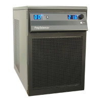
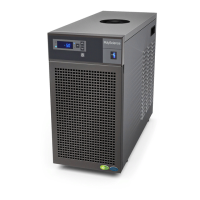
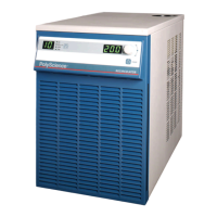
The Chiller incorporates an automatic safety to maintain outlet pressure below a valve-regulated
pressure. This valve is adjustable and is located inside the Chiller housing.
CAUTION: There are exposed fan blades inside the Chiller housing. Exercise extreme care
when accessing or adjusting any interior components.
WARNING: Hazardous voltages are present.
To access the high-pressure bypass valve, remove the two bolts at the upper left and right corners
of the Chiller’s rear panel, slide the top panel back about 2-3 inches, and lift off. The regulator valve
is located in the left rear corner of the unit.
The high-pressure bypass is adjusted as follows:
1. Set the low flow rate alarm value to zero (see Section 4.3.5, above). This will prevent the unit
from activating the flow alarm while you are adjusting the maximum pressure setting.
2. Completely block the Chiller’s outlet flow. This should cause the outlet pressure to rise.
3. Set the Pressure/Flow Rate display to read either PSI or kPa.
4. Rotate the handle on the pressure valve until the desired maximum pressure setting is
displayed on the Pressure/Flow Rate display.
5. Reset the flow alarm value to the previous setting.
6. Return the Pressure/Flow Rate display to the previous setting.
7. Replace the top panel of the Chiller, being sure to secure the bayonet-style prongs on the front
of the panel in the openings at the front of the unit. Reinsert the two bolts that secure the top
panel to the rear panel of the unit.
4.10 Enabling/Disabling the Local Lockout
This feature is used to prevent unauthorized or accidental changes to set point and other operational
values. When enabled, the values for the functions described in Sections 4.1, 4.2, 4.3, and 4.5 can
be displayed, but not changed.
To enable the local lockout, press and hold the Select/Set Knob until LLO is displayed
(approximately 5 seconds). Once enabled, LLO will appear momentarily when the Select/Set Knob
is pressed to display the set point.
To disable the local lockout, press and hold the Select/Set knob until CAn appears momentarily as
local lockout status changes from enabled (LLO) to disabled (approximately 5 seconds).
NOTE: The Local Lockout feature does not prevent set point changes entered via the RS232
interface.
 Loading...