4PM-1440BV v3 2020-10 Copyright © 2020 Quality Machine Tools, LLC
COOLANT TANK
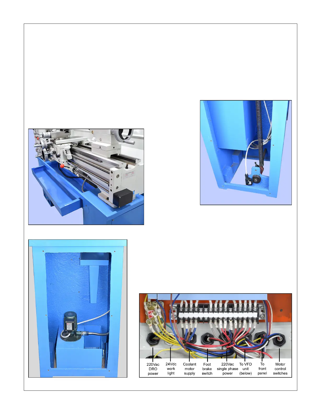
Inspect the coolant tank and pump assembly in the RH cabi-
net, Figure 1-4. The tank may have become dislodged in ship-
ment. Level it if necessary. Check that the footbrake spindle is
not pressing on the side of the tank. Reposition the spindle if
necessary.
Figure 1-3 Chip tray
Figure 1-4 Coolant tank
CLEANUP
Metal surfaces may have been protected by thick grease and/
or paper. Carefully remove these using a plastic paint scraper,
disposable rags and a light-oil such as WD-40.
available. If not, use the most reliable level on hand. Check and
adjust level front-to-back across the bed using a matched pair
of spacer blocks to clear the Vee tenons on the bed ways. The
blocks need to be at least 1/4 inch thick, ground or otherwise
accurately dimensioned. Alternatively, check for level on the
ground surface of the cross slide as the carriage is traversed
from end to end. See also "Aligning the Lathe" in Section 4.
FOOTBRAKE INTERLOCK
The lathe will not run if the footbrake switch fails to close when
the foot treadle is released (brake OFF). This switch is locat-
ed inside the LH stand cabinet. Check that the D-shape cam
operates the switch when the treadle is pressed, Figure 1-5.
CHIP TRAY
Check that the chip tray, Figure 1-3, can be pulled forward
without snagging coolant hoses and worklight wiring. Use ca-
ble ties if necessary.
Figure 1-5 Footbrake switch
ELECTRICAL CONNECTIONS
As shipped, the PM-1440BV is set for 220 Vac single phase
power.
Read Initial Checks, below, before connecting power
Remove the upper rear cover from the LH cabinet. If the lathe
did not come with a pre-installed power cord, connect the pow-
er source through a strain relief bushing to the port shown in
Figure 1-6 using 12 AWG (minimum) 3-wire cord. The 220V
input is identied as L, N at left of the connector strip.
Figure 1-6 Connections to upper electrical box

 Loading...

