10
PM 728V-T v2 2020-10 Copyright © 2020 Quality Machine Tools, LLC
Two tools are required to install or remove R8 tooling: an 11 mm
wrench for the square drawbar nut, and the supplied C-wrench
which engages in ats at the bottom end of the spindle.
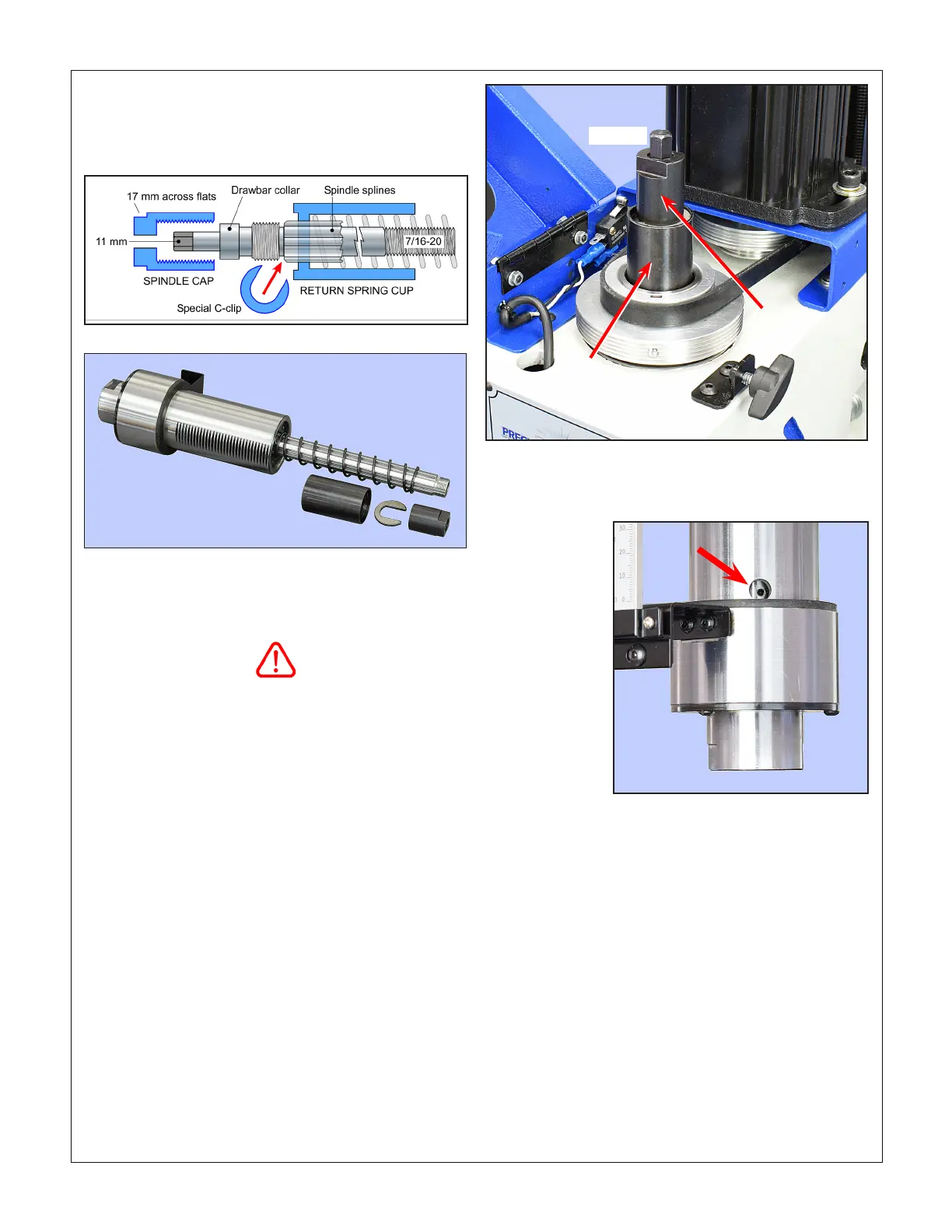
Figure 3-5 Two-step belt drive
The drawbar collar, Figure 3-2, must be
UNDER the spindle cap, as shown
Removing R8 tooling
Protect the table, vise or workpiece under the spindle with rags
or scrap wood. Why? Because they can easily be damaged by
falling tools and drill chucks. The cutting tool itself can also be
damaged in the same way.
Lock the spindle with the C-wrench, loosen the drawbar one
turn or less, just enough to unseat the taper, then tap the top
of the drawbar with a brass or dead-blow hammer to break the
taper seal. Unscrew the drawbar with one hand while support-
ing the R-8 device with the other hand.
R8 tooling is located in the spindle bore by an M4 x 6 mm
long set screw. If it is dicult or impossible to insert the
R8 device, chances are the set screw is in too far. Rotate
the spindle by hand to expose the screw, Figure 3-6, then
back it out a fraction of a turn using a 2 mm hex wrench.
Hand rotate the spindle again to check that the screw
clears the inside surface of the quill.
INSTALLING AND REMOVING TOOLING
The spindle and drawbar are designed for R-8 taper collets,
drill chucks and other arbors with the standard 7/16”-20 inter-
nal thread.
Figure 3-4 Spindle disassembled (drawbar omitted)
Figure 3-3 Spindle schematic
Return
spring
cup
Spindle
cap
Drawbar
Figure 3-6 Collet set screw
Installing R8 tooling
Install the R-8 device, then hand-thread the drawbar into it until
the drawbar collar bottoms on the splined spindle (on the ma-
chine itself this action is concealed by the spindle cap, Figure
3-3). Fully tighten the drawbar with an 11 mm wrench, while at
the same time holding the spindle stationary with the special
C-wrench, page 7. [Do NOT try to hold the spindle using the
ats on the spindle cap.]

 Loading...
