12
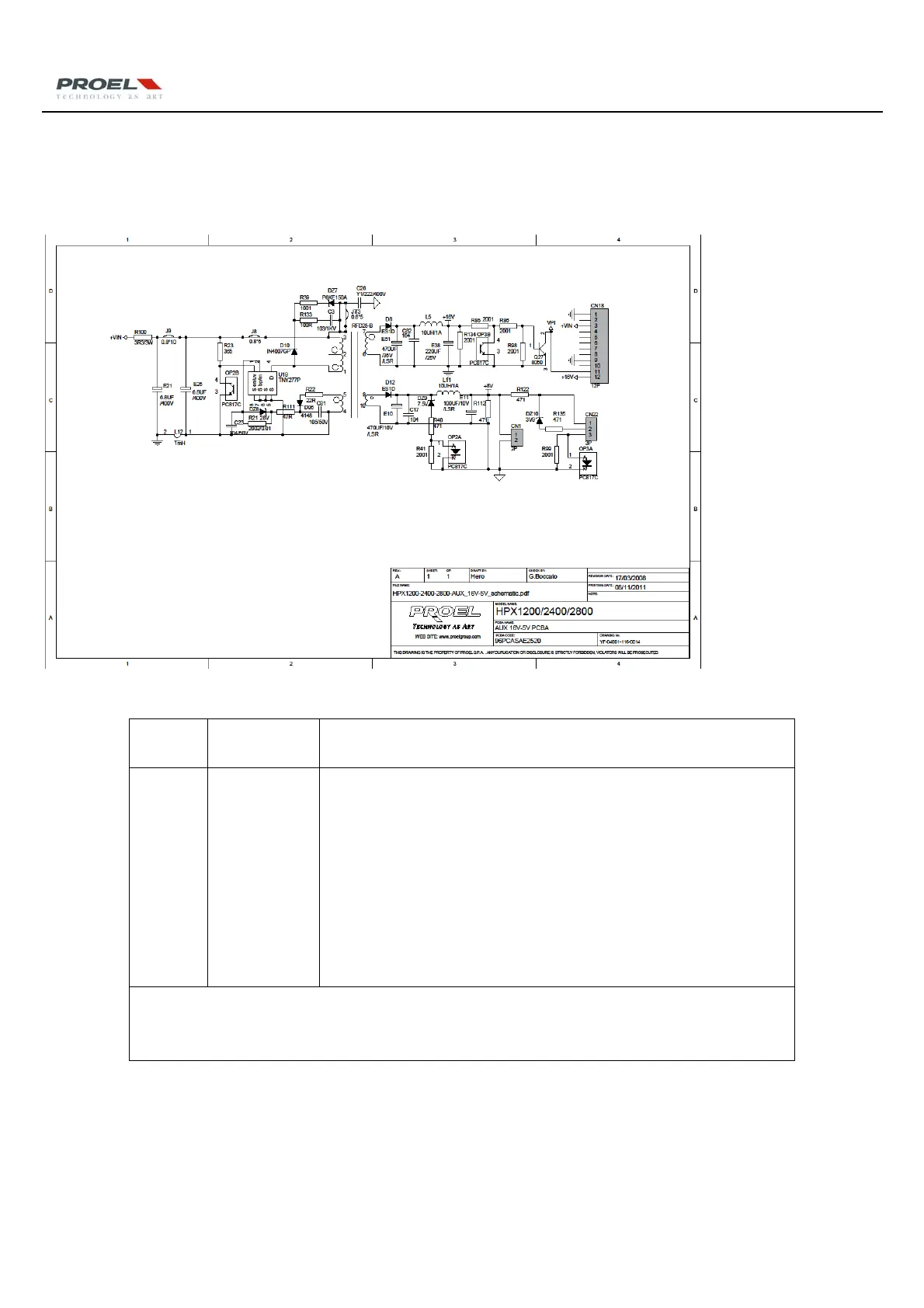
7 HPX1200/2400/2800 Malfunction Analysis on Aux Power
SupplyBoard
7.1HPX1200/2400/2800CircuitDiagramofAuxpowersupplyModule
7.2MalfunctionAnalysisonAuxpowersupply
Sequence
No.
Circuit
Function
Failure
1
AuxPower
SupplyBoard
‐ STYLEDisoff;theequipmentisunavailabletostart.
‐ Checkthecircuit,seeifthe CN1pinandthecopperfoilofAux Power
Supplyisbroken;
‐ When amplifier connects to power supply, the Aux Power Supply
(self‐activated switch) will start
to work, provide two group standby
power supply +5V & +16V. Among them, CN3/+5V is for power on/off
led (orange), CN1 +16V is for the main power control board, the main
poweron/offiscontrolled by the CN4in plug.WhentheCN4isclosed,
OP3/817willbeconnected,Q2/8050
willbedownedtolowlevel(VPI).
RepairingGuide:
Whenrepairingthepowerboard,pleasecuttheDC/300Vfuse,seriesconnecta100W—200Wlampto
startthemachine,preventingthedamageofrelateddevicewhenrepairing.
 Loading...