07 16BISV0903
2.3 Equipment Interfa ce Instruction
This section details the front and back panel of the interface functions.
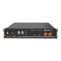
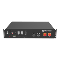
US2000 (VERSION B) Product Front Interface
Power Switch
Power Switch: to turn ON/OFF the whole battery BMS standby, no power output.
RUN
RUN light: to show the Power Switc h is ON, and the BMS has electricity (No power).
Start
Start Button: to start the battery m odule, Power output ready.
ADD Switch (5)
ADD Switch: 4 ADD switches, to definite different address code for each battery module
when multiple modules are cascaded, up to 8 addresses. But if all the battery cable connectionis
correct, the ADD will distribute themselves, and not necessary to set.
Console
Console Comm unication Terminal: (RJ11 po rt) follow RS232 protocol, for manufacturer or
professional engine er to debug or service.
CAN
CAN Communication Terminal: (RJ45 port) follow CAN protocol, for output batteries
information.
 Loading...