EasyManuals Logo
Home>QTech>Switch>QSW-8200 series

QTech QSW-8200 series User Manual

Default Icon
29 pages
To Next Page IconTo Next Page
To Previous Page IconTo Previous Page
Page #12 background imageLoading...
Page #12 background image
User Manual
Chapter 1. Introduction 12
www.qtech.ru
PIN3: -52V DC power cathode input
PIN4: 0V DC power positive electrode input
PIN5: 0V DC power positive electrode input
1.4.4 Status LEDs
LEDs of QSW-8200 show the corresponding state.
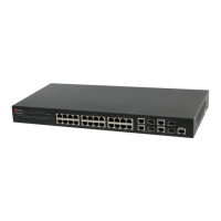
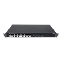
In mainboard of QSW-8200-28T-AC/ QSW-8200-28T-AC-DC/ QSW-8200-28T-POE-AC-DC/ QSW-
8200-52T-AC/ QSW-8200-52T-AC-DC/ QSW-8200-52T-AC-DC/ QSW-8200-52T-POE-AC-DC the
LEDs include two parts, one is 24/48 1000M interface LEDs, they show each port state at RJ45
plug-in, each port corresponds a LED with double colors.
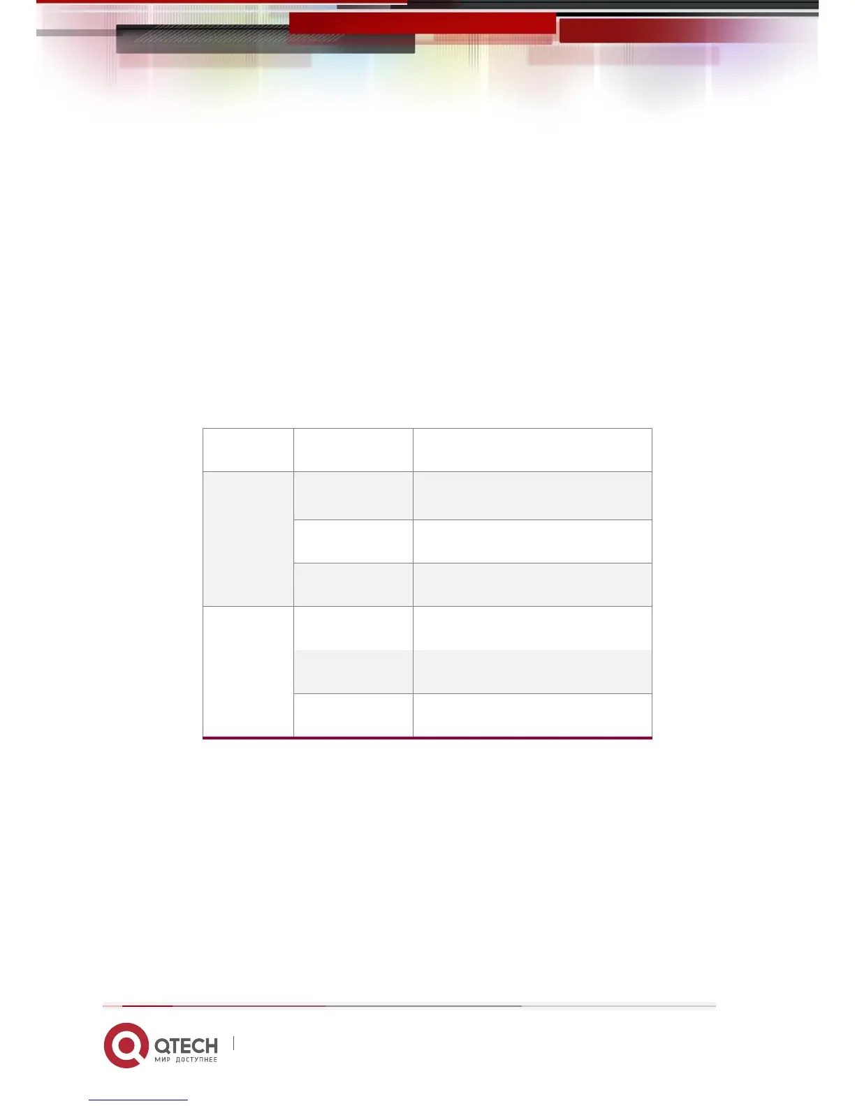
Table 1-2 Port LEDs
LED
Status
Description
Red
On
PoE power output
Off
no PoE power output
Blink
Send or receive the data
Green
On
Port in link state
Off
Port not in link state
Blink
Send or receive the data
The other is system LEDs, they are used to show the work status of the system at the right of
front panel.

Questions and Answers:

Question and Answer IconNeed help?

Do you have a question about the QTech QSW-8200 series and is the answer not in the manual?

QTech QSW-8200 series Specifications

General IconGeneral
BrandQTech
ModelQSW-8200 series
CategorySwitch
LanguageEnglish

Related product manuals