LTE Module Series
EC20 Mini PCIe Hardware Design
EC20_Mini_PCIe_Hardware_Design Confidential / Released 18 / 36
3.4. USIM Card Interface
The following table shows the pin definition of the USIM card interface.
Table 6: USIM Pin Definition
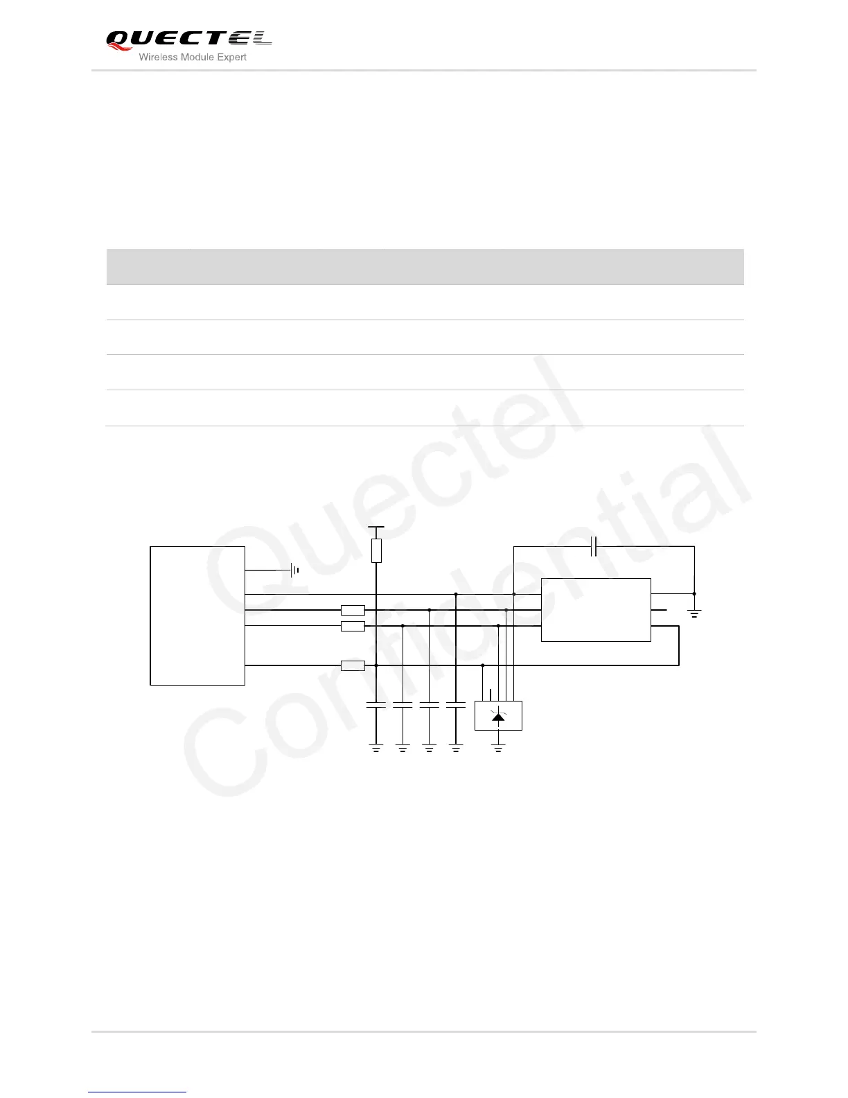
EC20 Mini PCIe supports 1.8V and 3.0V USIM cards. The following figure shows the reference design of
the 6-pin USIM card.
Figure 4: Reference Circuit of the 6-Pin USIM Card
In order to enhance the reliability and availability of the USIM card in your application, please follow the
criteria below in the USIM circuit design:
Keep layout of USIM card as close to the module as possible. Assure the length of the trace as less
than 200mm as possible.
Keep USIM card signal away from RF and power supply alignment.
Keep the width of ground and USIM_VDD no less than 0.5mm to maintain the same electric potential.
The decouple capacitor of USIM_VDD should be less than 1uF and must near to USIM holder.
 Loading...