LTE Module Series
EG21-G Hardware Design
EG21-G_Hardware_Design 33 / 100
Figure 8: Star Structure of the Power Supply
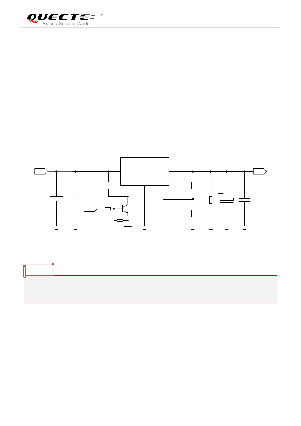
3.6.3. Reference Design for Power Supply
Power design for the module is very important, as the performance of the module largely depends on the
power source. The power supply should be able to provide sufficient current up to 2A at least. If the
voltage drop between the input and output is not too high, it is suggested that an LDO should be used to
supply power for the module. If there is a big voltage difference between the input source and the desired
output (VBAT), a buck converter is preferred to be used as the power supply.
The following figure shows a reference design for +5V input power source. The typical output of the power
supply is about 3.8V and the maximum load current is 3A.
In order to avoid damaging internal flash, please do not switch off the power supply when the module
works normally. Only after the module is shut down by PWRKEY or AT command, then the power supply
can be cut off.
3.6.4. Monitor the Power Supply
AT+CBC command can be used to monitor the VBAT_BB voltage value. For more details, please refer to
document [2].

 Loading...
